honeywell t5 installation manual pdf

Honeywell T5 Installation Manual PDF: A Comprehensive Guide

Honeywell T5 Smart Thermostat manuals, including installation instructions, are readily available as free PDF downloads, offering step-by-step guidance for a seamless setup experience.

Understanding the Honeywell T5 Smart Thermostat

The Honeywell T5 Touchscreen Thermostat represents a significant leap in home climate control, offering a blend of programmability, Wi-Fi connectivity, and user-friendly operation. This smart thermostat empowers homeowners to remotely manage their heating and cooling systems, leading to enhanced comfort and potential energy savings. Its intuitive touchscreen interface simplifies operation, while compatibility with various smart home ecosystems—like Amazon Alexa and Google Assistant—integrates seamlessly into modern lifestyles.

Key features include customizable scheduling, geofencing capabilities, and detailed energy reports. The T5 learns your preferences over time, optimizing temperature settings for maximum efficiency. Understanding these features is crucial before beginning installation, as proper configuration unlocks the thermostat’s full potential. The installation process itself, detailed in the provided PDF manuals, is designed to be accessible to many homeowners, though professional installation is always an option.

What’s Included in the Box

Upon opening your Honeywell T5 Smart Thermostat package, you’ll find several key components essential for a successful installation. These include the T5 Smart Thermostat unit itself, featuring a vibrant touchscreen display; Crucially, verify the presence of the Quick Install Guide, providing a condensed overview of the setup process. Some models also include a C-Wire Power Adapter, vital for systems lacking a common (C) wire – check the packaging for a symbol after “T5” to confirm inclusion.

The box also contains mounting screws and wall anchors for secure baseplate installation. Detailed installation manuals, available as downloadable PDFs, offer comprehensive guidance. It’s important to note that not all T5 models include the C-Wire adapter; if yours doesn’t, you may need to purchase one separately. Familiarizing yourself with these contents before starting ensures a smooth and efficient installation experience.

Tools You Will Need for Installation

Successfully installing your Honeywell T5 Smart Thermostat requires a few essential tools. A screwdriver – both Phillips head and flathead – is paramount for removing your old thermostat and securing the T5 baseplate. A small level ensures the thermostat is mounted straight, contributing to a professional appearance and accurate temperature readings. For wiring, wire strippers or cutters are necessary to prepare the existing thermostat wires for connection.

A digital multimeter can be incredibly helpful for verifying power is off before you begin and for troubleshooting potential wiring issues. A smartphone or tablet with access to the App Store or Google Play is crucial for downloading the Honeywell Home app, essential for setup and control. Finally, a camera or phone camera is recommended to photograph your existing wiring configuration before disconnecting anything – this serves as a vital reference during the installation process.

Compatibility Check: Ensuring a Smooth Installation

Before beginning the installation, verifying compatibility is crucial for a hassle-free experience with your Honeywell T5 Smart Thermostat. The T5 is generally compatible with most 24V heating and cooling systems, including furnaces, heat pumps, and air conditioners. However, it’s essential to confirm your system doesn’t utilize line voltage (120V or 240V) as the T5 isn’t designed for these systems.

Specifically, check if you have a common wire (C-wire). Some older systems lack a C-wire, but a Honeywell Home Power Adapter is included with certain T5 models to provide power without one. Confirm your model package includes it if needed – models after ‘T5’ without a C-wire symbol don’t. Review the Honeywell website or the installation manual PDF for a comprehensive compatibility list and detailed guidance on identifying your system type.

Step-by-Step Installation Process

The installation involves removing your old thermostat, identifying existing wiring, connecting the Honeywell T5, and mounting the baseplate for optimal performance.

Removing Your Old Thermostat: Preparation is Key

Before beginning the installation, carefully photograph your existing thermostat’s wiring – this is crucial for accurate reconnection to the Honeywell T5. Power off your HVAC system at the breaker to avoid electrical shock. Gently remove the thermostat cover, revealing the wiring terminals.

Label each wire with the corresponding terminal designation; this step prevents confusion during the new thermostat’s wiring process. Disconnect the wires one at a time, noting their positions. Keep a detailed record of the wiring configuration, as it will be essential for correctly connecting the T5.

Once all wires are disconnected, carefully remove the old thermostat baseplate from the wall. Ensure the wall surface is clean and prepared for mounting the new Honeywell T5 baseplate. Proper preparation minimizes potential issues during the installation and ensures a secure fit.

Identifying Existing Wiring

After removing your old thermostat, carefully examine the wires. Common wire colors include red (power), white (heat), yellow (cooling), green (fan), and blue or black (common – C-wire). However, wire colors can vary, so relying solely on color isn’t sufficient.

Refer to the photograph you took earlier and the labels you applied to each wire. Match each wire to its corresponding terminal on the old thermostat. Understanding the function of each wire is vital for correct installation of the Honeywell T5.

If you find a “C-wire” (common wire), it provides continuous power to the thermostat. If a C-wire isn’t present, a power adapter might be necessary (included with some T5 models). Accurately identifying each wire ensures a smooth and functional Honeywell T5 setup.

Connecting the Honeywell T5 Thermostat Wiring

Using your wire labels and the Honeywell T5’s wiring diagram, connect each wire to the corresponding terminal on the thermostat’s baseplate. Ensure each wire is securely inserted into the terminal – a gentle tug confirms a solid connection. Match the wire functions identified previously (red to R, white to W, yellow to Y, green to G, and blue/black to C, if present).

Double-check all connections against your photograph and the wiring diagram. Incorrect wiring can damage your HVAC system or the thermostat. If you’re unsure about any connection, consult a qualified HVAC technician.

Properly connected wiring is crucial for the Honeywell T5 to communicate effectively with your heating and cooling system, enabling remote control and scheduling features.

C-Wire Considerations and Power Adapter

The Honeywell T5 often requires a C-wire (common wire) for consistent power. If your existing thermostat lacks a C-wire, the included Power Adapter can provide the necessary power. Locate the adapter under the thermostat packaging – models after T5 may not include it.

To use the adapter, connect the blue wire from the thermostat baseplate to the adapter, and then connect the adapter to the R and C terminals on your furnace/HVAC control board. Carefully follow the adapter’s installation instructions.

Without a consistent power source, the Honeywell T5 may experience connectivity issues or require frequent battery changes. The C-wire or Power Adapter ensures reliable operation and access to all smart features.

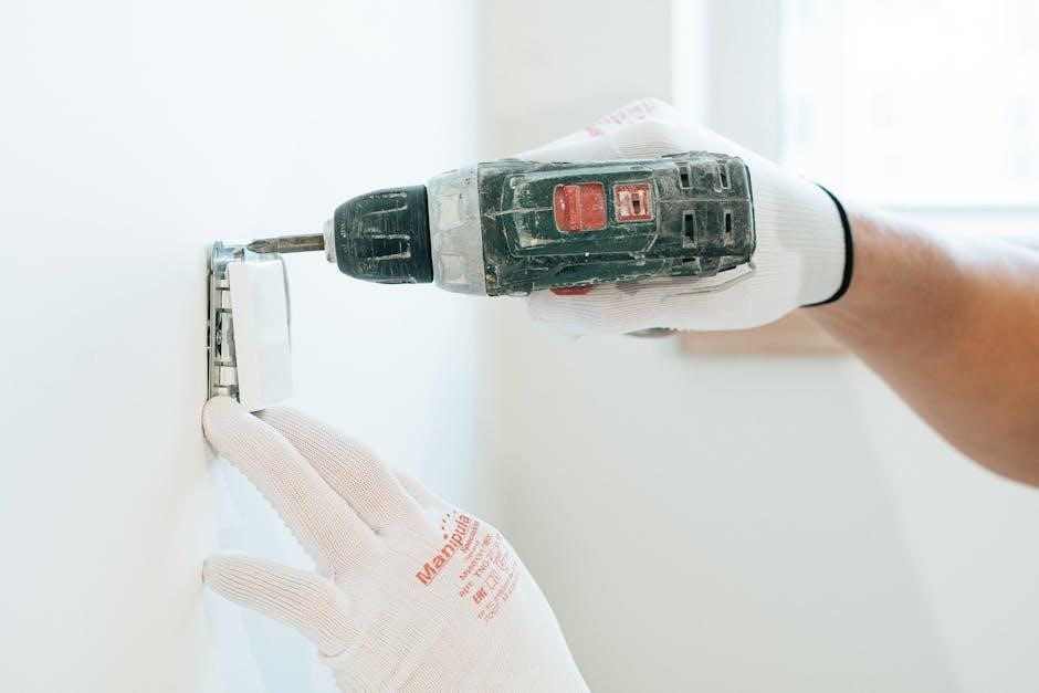
Mounting the T5 Thermostat Baseplate

After wiring, carefully mount the Honeywell T5 thermostat baseplate to the wall. Ensure it’s level for a professional appearance and proper touchscreen functionality. Use the screws provided in the box, utilizing existing holes whenever possible to minimize wall damage.

If new holes are necessary, use appropriate wall anchors for secure mounting. Gently snap the T5 thermostat display onto the mounted baseplate. Verify a snug fit, ensuring all wiring connections remain secure and hidden from view.

Double-check that the baseplate is firmly attached to the wall before proceeding. A stable base is crucial for long-term reliability and prevents potential damage to the thermostat or your wall. Refer to the installation guide PDF for detailed diagrams.

Honeywell Home App Setup

Download the Honeywell Home app from the App Store or Google Play to configure your system and connect your new T5 thermostat to your smartphone easily.

Downloading and Opening the Honeywell Home App

Getting Started with the App: The initial step in connecting your Honeywell T5 Smart Thermostat is downloading and opening the Honeywell Home app. This application serves as the central hub for controlling and monitoring your home’s temperature remotely. You can easily find the app by searching “Honeywell Home” on either the Apple App Store (for iOS devices) or Google Play Store (for Android devices).

Once downloaded, tap the app icon to launch it. If you’re a new user, you’ll be prompted to create an account. Existing users can simply sign in with their credentials. The app’s interface is designed for intuitive navigation, guiding you through the setup process. After logging in, the app will automatically begin searching for nearby Honeywell thermostats, including your newly installed T5 model. Ensure your smartphone’s Bluetooth is enabled to facilitate this discovery process.

The app will display “Thermostat Found” when it locates your T5. Tap “SET UP NOW” to proceed with the configuration.

Thermostat Discovery and Account Setup

Upon opening the Honeywell Home app, it initiates a search for your T5 Smart Thermostat. This discovery process relies on Bluetooth connectivity, so ensure it’s enabled on your smartphone. The app intelligently scans for compatible devices in close proximity, streamlining the setup. If the thermostat isn’t immediately detected, verify it’s powered on and within range.

If you’re a first-time user, the app will guide you through account creation. This involves providing a valid email address and creating a secure password. An existing account allows for seamless integration with other Honeywell Home devices. Account setup is crucial for remote access and personalized settings.

Once logged in or after creating an account, the app should display your T5 under “Thermostat Found.” Selecting “SET UP NOW” initiates the configuration process, linking your thermostat to your Honeywell Home account and preparing it for Wi-Fi connection.

Connecting the T5 Thermostat to Wi-Fi

After account setup, the Honeywell Home app prompts you to connect your T5 Thermostat to your home’s Wi-Fi network. This enables remote control and access to smart features. The app will display a list of available Wi-Fi networks; select yours from the list, ensuring it’s a 2.4 GHz network for optimal compatibility.

You’ll then be prompted to enter your Wi-Fi password. Double-check for accuracy, as incorrect credentials will prevent connection. The thermostat will attempt to connect, and the app will display a progress indicator. A successful connection is confirmed within the app, typically accompanied by a visual cue on the thermostat’s display;

If the connection fails, verify your password, router functionality, and thermostat proximity to the router; A stable Wi-Fi signal is essential for reliable performance and access to all smart features.

System Configuration within the App

Once the T5 Thermostat is connected to Wi-Fi, the Honeywell Home app guides you through system configuration. This crucial step involves defining your home’s heating and cooling system type – options include forced air, heat pump, and radiant heat. Accurate selection ensures proper operation and efficient energy use.

The app will then ask about fuel source (gas, electric, oil) and the number of heating/cooling stages. These details optimize the thermostat’s control algorithms. You’ll also set location for geofencing features and configure temperature preferences.

Carefully review each setting, as incorrect configuration can impact comfort and energy savings. The app provides helpful explanations and prompts throughout the process, ensuring a tailored setup for your specific home and needs.

Using the Honeywell Home App

The Honeywell Home app unlocks remote control and monitoring of your T5 Thermostat, offering scheduling, geofencing, and convenient temperature adjustments from anywhere.

Navigating the App Interface

The Honeywell Home app boasts a user-friendly interface designed for intuitive control of your T5 Smart Thermostat. Upon opening, the main dashboard prominently displays your thermostat’s current temperature and operating mode – heating, cooling, or auto. A large, easily adjustable temperature slider allows for quick manual adjustments.

Below the temperature controls, you’ll find access to scheduling features, enabling you to create customized heating and cooling schedules tailored to your lifestyle. The app’s menu, typically located in the corner, provides access to device settings, account information, and helpful resources.

Within the settings, you can manage Wi-Fi connectivity, adjust thermostat display preferences, and configure alerts for temperature fluctuations or system issues. The app also provides a historical view of your energy usage, allowing you to track savings and optimize your settings. Exploring the app’s various sections will quickly familiarize you with its capabilities, ensuring a smooth and efficient home comfort experience.

Scheduling and Geofencing Features

The Honeywell Home app empowers you to create personalized heating and cooling schedules, optimizing comfort and energy savings. You can define different temperature settings for various times of the day and days of the week, aligning with your routine. For example, lower temperatures while you’re at work and increase them before your return.

Beyond scheduling, the app’s geofencing feature adds another layer of automation. By setting a virtual boundary around your home, the thermostat automatically adjusts the temperature based on your smartphone’s location.

As you leave the geofenced area, the thermostat can switch to an energy-saving mode, and as you approach, it will pre-heat or pre-cool your home for optimal comfort. This intelligent feature eliminates wasted energy and ensures a welcoming environment upon arrival. Both scheduling and geofencing are easily configured within the app’s intuitive interface.

Remote Control and Monitoring

A key benefit of the Honeywell T5 Smart Thermostat is its ability to be controlled remotely via the Honeywell Home app. Whether you’re traveling or simply relaxing in another room, you can adjust the temperature, change modes (heat, cool, auto, off), and view current system status from your smartphone or tablet.

The app provides real-time monitoring of your home’s temperature, humidity levels, and energy usage. This data allows you to identify potential energy-saving opportunities and optimize your heating and cooling habits. You’ll receive alerts and notifications regarding system performance, such as extreme temperature fluctuations or filter change reminders.

Remote access ensures comfort and peace of mind, allowing you to maintain a comfortable home environment even when you’re away. The Honeywell Home app delivers convenient control and valuable insights into your home’s climate.

Troubleshooting Common Issues

The Honeywell T5 manual PDF offers solutions for wiring problems, connectivity glitches, and other issues, ensuring a smooth user experience and optimal thermostat performance.

Wiring Problems and Solutions

The Honeywell T5 Installation Manual PDF provides detailed diagrams and troubleshooting steps for common wiring issues encountered during setup. A frequent concern is the absence of a C-wire, which provides continuous power; the manual explains utilizing the included Power Adapter in such cases, located under the thermostat within the box.

If the thermostat isn’t powering on, double-check all wire connections against the wiring diagram in the PDF. Ensure wires are securely inserted into the correct terminals. Incorrect wiring can lead to system malfunctions or damage. The manual also addresses scenarios where the thermostat doesn’t recognize existing wiring, suggesting a reset and re-scan within the Honeywell Home app.

For systems with heat pumps, specific wiring configurations are detailed in the manual to ensure proper operation of both heating and cooling. Always consult the PDF for your specific system type before attempting any wiring changes. Safety is paramount; always turn off power to the HVAC system at the breaker before working with wiring.

Connectivity Glitches and Fixes

The Honeywell T5 Installation Manual PDF offers solutions for common connectivity problems experienced during setup and daily use. If the thermostat fails to connect to Wi-Fi, the manual advises verifying your network credentials and ensuring a strong Wi-Fi signal. Restarting both your router and the thermostat are often effective first steps.

If the thermostat appears “offline” in the Honeywell Home app, check the app for updates and ensure your smartphone has a stable internet connection. The manual details troubleshooting steps within the app itself, including re-discovering the thermostat and re-establishing the Wi-Fi link.

For persistent connectivity issues, the PDF suggests checking for potential interference from other wireless devices. Resetting the thermostat to factory settings (as outlined in the manual) can also resolve stubborn connection problems. Finally, the manual directs users to Honeywell’s support website for further assistance and FAQs.

Accessing Manuals and User Guides (PDF)

Finding the Honeywell T5 Installation Manual PDF is straightforward. Honeywell provides a comprehensive library of manuals and user guides directly on their official website. A quick online search for “Honeywell T5 Smart Thermostat manual PDF” will also yield direct links to downloadable documents.

These PDFs include detailed installation instructions, troubleshooting guides, and explanations of all thermostat features. You’ll find the Owner’s manual, Product information sheets, and specific installation guides readily available for free download. The manuals cover various T5 models, ensuring you find the correct documentation for your specific device.

Honeywell’s website allows filtering by product type and model number, simplifying the search process. Downloading the PDF allows offline access to crucial information during installation or when troubleshooting, providing a convenient resource for Honeywell T5 users.

Continue Reading

manual for ridgid shop vac

This document serves as the comprehensive owner’s manual for Ridgid wet/dry vacs‚ detailing crucial safety guidelines‚ assembly steps‚ operational instructions‚ and essential maintenance procedures․

What is a Ridgid Shop Vac?

Ridgid Shop Vacs are powerful‚ versatile wet/dry vacuum cleaners designed for both home and professional use․ These robust machines efficiently tackle a wide range of cleanup tasks‚ from everyday dust and debris to wet spills and larger construction messes․ Available in various sizes and power levels‚ including cordless options utilizing the Ridgid 18-Volt system‚ they offer exceptional suction and durability․ The manual emphasizes safe operation and proper maintenance for optimal performance and longevity of your Ridgid vacuum․

Why Use a Manual?

Consulting the manual before operating your Ridgid Shop Vac is paramount for safety and optimal performance․ It details critical safety precautions to prevent injuries and ensures proper usage of all features․ The manual guides assembly‚ explains operation for both wet and dry pickup‚ and outlines essential maintenance procedures like filter cleaning and tank emptying․ Ignoring these instructions could lead to damage‚ reduced efficiency‚ or potential hazards – read it thoroughly!

Understanding Your Ridgid Shop Vac Model

This section focuses on identifying your specific Ridgid Shop Vac model‚ understanding its key features‚ and reviewing its technical specifications for effective operation․

Identifying Your Model Number (WD1665 & Others)

Locating your Ridgid Shop Vac’s model number is crucial for accessing specific documentation and support․ The model number‚ such as WD1665‚ is typically found on a sticker affixed to the vacuum’s tank․ This sticker often includes the serial number as well․ Knowing your exact model ensures you have the correct parts diagrams‚ troubleshooting advice‚ and warranty information readily available․ Referencing this number when contacting customer service streamlines the support process‚ guaranteeing accurate assistance tailored to your specific unit․

Key Features and Specifications

Ridgid Shop Vacs boast robust construction‚ resisting dents‚ rust‚ and corrosion‚ ideal for demanding jobs․ Many models‚ like the 16-gallon WD1665‚ deliver 5․0 peak horsepower for powerful suction․ Inclusion of an 18-volt battery and charger provides cordless convenience․ Features include large capacities‚ versatile attachments‚ and efficient filtration systems․ Specifications vary by model‚ encompassing tank size‚ airflow (CFM)‚ water lift (inches)‚ and cord length – all detailed in your owner’s manual․

Assembly and Setup

Proper assembly involves securely attaching the hose and desired accessories‚ ensuring a tight seal for optimal performance‚ as detailed within the provided manual’s instructions․

Attaching the Hose and Accessories

The manual clearly illustrates how to connect the hose to the vacuum’s inlet‚ ensuring a firm and secure fit to prevent suction loss during operation․ Various accessories‚ like nozzles and extension wands‚ easily attach to the hose end․ Proper attachment is vital for efficient cleaning‚ whether tackling wet or dry messes․ The manual emphasizes checking connections before each use to maintain peak performance and avoid disruptions․ Incorrectly attached accessories can significantly reduce the vacuum’s effectiveness and potentially cause damage․

Filter Installation and Types

The Ridgid shop vac manual details proper filter installation‚ crucial for both wet and dry pickup․ Different filter types exist – standard for dry debris‚ and specialized filters for fine dust or wet applications․ Correct installation ensures optimal filtration and prevents motor damage․ Regularly inspect filters; a clogged filter reduces suction power․ The manual advises replacing filters periodically to maintain peak performance and prolong the vacuum’s lifespan‚ safeguarding against potential issues․

Operating Instructions

The Ridgid shop vac manual provides clear instructions for powering the unit on and off‚ alongside specific procedures for both efficient wet and dry pickup operations․

Powering On and Off

Before operation‚ ensure the shop vac is properly assembled with a filter installed and the tank securely positioned․ To power on‚ simply plug the vacuum into a grounded electrical outlet․ The power switch is typically located on the unit’s housing‚ clearly marked for easy access․ Press the ‘On’ position to initiate suction․

To turn off‚ press the switch to the ‘Off’ position․ Always disconnect the power cord from the outlet when not in use‚ during filter changes‚ or when performing any maintenance․ This prevents accidental activation and ensures safety․

Wet Pickup Procedures

When collecting liquids‚ remove the dry filter to prevent damage and ensure optimal suction․ Utilize the foam sleeve‚ specifically designed for wet pickup‚ around the filter cage․ Position the vacuum nozzle directly over the liquid source‚ avoiding splashing․

Monitor the tank’s fill level frequently to prevent overflow․ Once full‚ promptly shut off the vacuum and carefully dispose of the collected liquid․ Always clean the tank thoroughly after wet pickup to prevent corrosion․

Dry Pickup Procedures

For dry debris‚ ensure the standard filter is securely installed within the filter cage․ This prevents dust and particles from bypassing the filter and re-entering the air․ Position the vacuum nozzle close to the surface for efficient pickup‚ adjusting the suction control if needed․

Regularly monitor the filter’s condition; a clogged filter reduces suction․ Empty the tank when it’s approximately two-thirds full to maintain performance and prevent overflow․

Maintenance and Care

Consistent cleaning of the filter and timely emptying of the tank are vital for optimal performance and longevity of your Ridgid shop vacuum․

Filter Cleaning and Replacement

Regular filter maintenance is crucial for maintaining suction power․ The manual details how to remove and clean both standard and specialty filters; typically‚ a wash and thorough drying are sufficient․ However‚ filters degrade over time and must be replaced․

Inspect filters frequently for damage or excessive wear․ Replacement frequency depends on usage‚ but annual replacement is recommended for typical use․ Using a dirty or damaged filter significantly reduces performance and can strain the motor․

Emptying the Tank

Before emptying‚ always power off and unplug the shop vac to prevent accidental activation․ The manual instructs users to carefully detach the tank‚ ensuring proper handling to avoid spills․ Dispose of collected debris responsibly‚ following local regulations․

Rinse the tank with water if necessary‚ ensuring it’s completely dry before reattaching․ Regular emptying maximizes suction and prevents overflow during operation‚ contributing to the longevity of the vacuum․

Long-Term Storage

When storing for extended periods‚ the manual advises thoroughly emptying and cleaning the tank to prevent mold or odor buildup․ Remove and clean the filter‚ storing it separately in a dry location․ Coil the hose neatly and secure it to prevent damage․

Store the shop vac in a cool‚ dry environment‚ away from direct sunlight and extreme temperatures to maintain its functionality and extend its lifespan․

Troubleshooting Common Issues

The manual details solutions for loss of suction‚ motor overheating‚ and electrical problems‚ offering guidance to resolve typical issues and maintain optimal performance․

Loss of Suction

If experiencing reduced suction‚ first check if the tank is full and empty it accordingly․ Inspect the hose for any blockages‚ kinks‚ or disconnections‚ ensuring a secure fit at all connection points․

Verify the filter is clean and properly installed; a clogged filter significantly restricts airflow․ Examine the intake opening for obstructions․ The manual emphasizes these checks as primary steps to restore optimal suction power‚ preventing motor strain and ensuring efficient cleaning performance․

Motor Overheating

Should the motor overheat‚ immediately power off the shop vac and unplug it from the electrical outlet․ Allow the motor to cool completely before attempting to restart it – this could take up to 30 minutes․

The manual cautions against continuous use without allowing for cooling periods‚ especially when tackling demanding tasks․ Ensure the filter is clean to prevent strain‚ and avoid picking up excessively fine particles that can restrict airflow and contribute to overheating․

Electrical Problems

If you encounter electrical issues‚ immediately disconnect the shop vac from the power source․ Never attempt to repair electrical components yourself; this poses a serious safety risk;

The manual stresses the importance of using a properly grounded outlet and avoiding extension cords unless absolutely necessary․ If the power cord is damaged‚ it must be replaced by a qualified technician to prevent shock or fire hazards․

Safety Precautions

The manual emphasizes reading all safety instructions before operation to prevent injury․ Always disconnect the vac before servicing‚ and never use it to pick up flammable liquids․

General Safety Guidelines

Before using your Ridgid shop vac‚ carefully read and understand this manual․ Always disconnect the power supply before changing accessories or performing maintenance․ Never operate the vacuum without a filter installed‚ and avoid picking up combustible materials like gasoline or other flammable liquids․

Ensure the work area is well-ventilated‚ and keep bystanders away during operation․ Do not use the vacuum outdoors in wet conditions‚ and always wear appropriate eye protection․ Inspect the cord regularly for damage‚ and avoid using an extension cord if possible․

Working with Flammable Liquids

This Ridgid shop vac is not designed for picking up flammable liquids․ Doing so presents a serious fire and explosion hazard․ Never vacuum gasoline‚ kerosene‚ diesel fuel‚ or other similar substances․ If flammable liquids have been spilled‚ ensure complete evaporation and ventilation before using the vacuum in the area․

Using this vacuum with flammable materials will void the warranty and could cause severe injury or property damage․ Prioritize safety and utilize appropriate methods for cleaning up hazardous spills․

Ridgid Shop Vac Accessories

A wide array of attachments are available‚ enhancing the vacuum’s versatility for various cleaning tasks‚ including crevice tools‚ brushes‚ and specialized nozzles․

Available Attachments and Their Uses

Ridgid shop vacs boast a diverse range of accessories to tackle any cleaning challenge․ Crevice tools excel at reaching tight spaces‚ while brush attachments gently loosen debris from surfaces․ Floor nozzles efficiently clean hard floors‚ and specialized attachments handle delicate upholstery․

Extension wands increase reach‚ and air/dust blowers clear debris from hard-to-access areas․ The manual details each attachment’s specific application‚ ensuring optimal performance and extending the vacuum’s functionality beyond basic cleanup․

Battery and Charger Information (for Cordless Models)

Cordless Ridgid shop vacs utilize the robust 18-volt Ridgid battery system‚ often including both battery and charger with initial purchase․ The manual emphasizes proper charging procedures for optimal battery life and performance․ It details LED indicators signifying charge status and potential issues․

Compatibility with other Ridgid 18V tools is a key benefit‚ allowing battery interchangeability․ Always refer to the manual for specific battery model compatibility and safety precautions during charging and use․

Warranty Information

Ridgid shop vacs are backed by the renowned Ridgid Lifetime Service Agreement‚ offering exceptional coverage․ The manual details claim procedures and warranty limitations․

Ridgid Lifetime Service Agreement

The Ridgid Lifetime Service Agreement is a standout benefit for owners‚ providing free parts and service for the life of the shop vac․ This exceptional guarantee‚ detailed within the manual‚ covers defects in materials and workmanship․ Registration is required to activate this benefit‚ ensuring continuous protection․ The agreement doesn’t cover misuse or abuse‚ but offers peace of mind knowing your investment is safeguarded against manufacturing flaws․ It’s a testament to Ridgid’s confidence in product durability and customer satisfaction․

How to Make a Warranty Claim

To initiate a warranty claim‚ as outlined in the manual‚ first register your Ridgid shop vac online or through the Ridgid app․ Retain your proof of purchase‚ as it’s essential documentation․ Contact Ridgid customer service via phone or their website to report the issue and receive claim instructions․ Be prepared to provide your model and serial number․ Ridgid will assess the claim and‚ if approved‚ provide repair or replacement․

Ridgid Shop Vac vs․ Competitors

The Ridgid 16-gallon shop vac offers maximum capacity and durability‚ resisting dents and corrosion‚ often bundled with a battery and charger for convenience․

Comparing Features and Performance

Ridgid shop vacs‚ as detailed in their manuals‚ frequently boast a 5․0 peak horsepower motor‚ providing robust suction for both wet and dry debris․ Competitors often vary in power‚ tank capacity‚ and included accessories․ The Ridgid models distinguish themselves with durable construction‚ resisting rust and dents‚ alongside the convenience of often including an 18-volt battery and charger․ Furthermore‚ the manuals emphasize safety features‚ a critical comparison point when evaluating performance alongside raw power and capacity․

Price Point Analysis

The Ridgid shop vac‚ according to available information‚ generally positions itself as a mid-range option‚ offering a balance between affordability and performance․ While some competitors may offer lower initial costs‚ Ridgid often includes valuable extras like the 18-volt battery and charger‚ effectively increasing its value proposition․ The lifetime service agreement‚ detailed in the manual‚ further enhances long-term cost savings‚ making it a competitive choice despite a potentially higher upfront price․

Finding Replacement Parts

Replacement parts for your Ridgid shop vac are readily available through numerous online retailers and local hardware stores‚ ensuring easy maintenance and repair․

Online Retailers

Numerous online retailers specialize in replacement parts for Ridgid shop vacs‚ offering a convenient shopping experience from the comfort of your home․ Major platforms like Amazon‚ eBay‚ and the official Home Depot website frequently stock a wide array of components‚ including filters‚ hoses‚ nozzles‚ and even complete replacement motors․ Always verify the part number from your manual to ensure compatibility before purchasing․ Several dedicated tool parts websites also provide specialized Ridgid vacuum parts‚ often with detailed diagrams and support to assist in identifying the correct replacement․

Local Hardware Stores

For those preferring in-person shopping‚ local hardware stores are excellent resources for Ridgid shop vac replacement parts․ Stores like Home Depot and Lowe’s typically maintain a stock of common components‚ such as filters‚ hoses‚ and attachments․ Smaller‚ independent hardware stores may also carry parts or be able to order them specifically for you․ Bringing your vacuum’s model number (found in the manual) ensures staff can quickly locate the correct replacements‚ saving you time and effort․

Understanding the Ridgid 18-Volt System

The Ridgid 18-volt battery and charger are often included‚ offering cordless convenience and compatibility with other Ridgid power tools within the same system․

Compatibility with Other Ridgid Tools

A significant benefit of the Ridgid 18-volt system is its broad compatibility․ The batteries powering cordless Ridgid shop vacs seamlessly integrate with a vast array of other Ridgid power tools‚ including drills‚ saws‚ and lighting․ This shared platform reduces costs‚ as you only need to invest in multiple tools‚ not numerous batteries and chargers․ Furthermore‚ it streamlines your workshop‚ offering convenient interchangeability and maximizing the versatility of your Ridgid tool collection․

Benefits of Cordless Operation

Cordless Ridgid shop vacs offer unparalleled freedom and convenience․ Eliminating the constraint of a power cord allows for easy maneuverability around workspaces‚ both indoors and outdoors․ This feature is particularly advantageous for jobsites or areas lacking readily available outlets․ Battery-powered operation also enhances safety‚ reducing trip hazards and providing greater flexibility during cleanup tasks‚ making it a practical choice․

Continue Reading

upunch time clock manual

Understanding Your uPunch Time Clock

uPunch Time Clocks streamline employee attendance, offering reliable time tracking solutions. These systems, like the Veriprint unit, integrate recording functions into daily operations.

Key benefits include accurate data collection, reducing payroll errors, and simplifying compliance. Models range from basic LCD displays to more advanced options.

Considerations involve potential issues with platforms like YouTube regarding content moderation, and ensuring data accuracy despite possible website errors or omissions.

What is a uPunch Time Clock?

uPunch Time Clocks represent a significant advancement in employee time and attendance management. Essentially, a uPunch clock is a physical device used by employees to record their clock-in and clock-out times, replacing traditional methods like paper timesheets. These clocks range in functionality, from simple models with LCD displays to more sophisticated systems capable of advanced data tracking.

Founded in 2005, alongside the rise of platforms like YouTube, uPunch has focused on providing reliable and accurate timekeeping solutions. The core function is to eliminate “buddy punching” and ensure precise payroll calculations. Many models, such as the Vintage Lathem Corporation punch clock, are designed for durability and long-term use.

Integration with software is a key aspect, allowing for easy downloading of time data and report generation. While online resources like basic calculators and music streaming services (YouTube Music) offer diverse functionalities, uPunch concentrates on the specific needs of time management.

Key Features and Benefits

uPunch Time Clocks boast several key features designed to optimize workforce management. These include accurate time tracking, minimizing payroll discrepancies and ensuring compliance with labor laws. User-definable features, like department and job code tracking, allow for detailed data analysis.

Benefits extend to simplified reporting, with capabilities for generating daily, weekly, and pay period reports. The integration with uPunch software streamlines data download and analysis, unlike the varied content found on platforms like YouTube. Expanded recording functionality, inherent in the Veriprint unit, enhances operational efficiency.

Furthermore, these clocks often offer tamper-resistant designs and robust build quality, exemplified by vintage models. While online calculators assist with basic math, uPunch focuses on complex timekeeping needs. Despite potential website inaccuracies, uPunch strives for reliable performance.

Setting Up Your uPunch Time Clock

Initial setup involves connecting the clock, configuring the date and time (currently 01/27/2026 08:24:12), and installing the necessary software for data management.

Initial Clock Setup

Unboxing and Inspection: Carefully unpack your uPunch Time Clock and verify all components are present, including the clock unit, power adapter, and any included accessories. Inspect for any physical damage that may have occurred during shipping.

Power Connection: Connect the provided power adapter to the clock and plug it into a standard electrical outlet. Ensure the connection is secure. The clock should power on automatically, displaying the initial setup screen.

Basic Configuration: The initial setup will guide you through essential configurations. This includes setting the correct date (currently 01/27/2026) and time (08:24:12). Accurate timekeeping is crucial for payroll accuracy. Follow the on-screen prompts to complete these steps.

Connectivity (if applicable): If your uPunch model supports connectivity (USB or Ethernet), follow the instructions to establish a connection to your computer. This is necessary for downloading time data and utilizing the uPunch software.

Language Selection: Choose your preferred language for the clock’s display and menu options. This ensures ease of use for all employees;

Employee Enrollment

Adding New Employees: Access the employee enrollment menu on your uPunch Time Clock. Typically, this involves navigating through the clock’s settings using the keypad or touchscreen. Each employee requires a unique identification number.

Employee ID Assignment: Assign a unique ID to each employee. This ID will be used for clocking in and out. Avoid using easily guessable numbers. Consider a sequential numbering system for easy management.

Name and Department (Optional): Enter each employee’s name and, if applicable, their department or job code. This information aids in reporting and data analysis. Department tracking enhances payroll processing.

Punch Card/Badge Setup: If your uPunch system uses physical punch cards or badges, assign each employee a card or badge and link it to their ID. Ensure the card/badge is properly formatted for the clock.

Verification: Double-check all entered information for accuracy. Incorrect employee data can lead to payroll errors and reporting inconsistencies. Accurate enrollment is vital.

Date and Time Configuration

Initial Date Setting: Upon initial setup, accurately set the current date on your uPunch Time Clock. Incorrect date settings will cause errors in time data recording and reporting. Access the date setting menu through the clock’s interface.

Time Format (12/24 Hour): Configure the time format to either 12-hour (AM/PM) or 24-hour (military time) based on your preference and company standards. Ensure all employees understand the chosen format.

Automatic Date/Time Updates: Some uPunch models support automatic date and time updates via network connection. Enable this feature if available to maintain accuracy and reduce manual adjustments.

Daylight Saving Time: Configure Daylight Saving Time settings to automatically adjust the clock during seasonal changes. Proper DST configuration prevents time discrepancies.

Verification: After configuration, verify the date and time displayed on the clock are correct. Regularly check these settings to ensure ongoing accuracy and reliable time tracking.

Using the uPunch Time Clock

Employee clocking is streamlined with uPunch, utilizing punch cards or biometric options for accurate timekeeping and efficient attendance management.

Clocking In and Out Procedures

To clock in, employees present their assigned time cards to the uPunch clock. Ensure the card is inserted correctly, with the magnetic stripe facing the appropriate direction, for accurate registration.

The clock will then imprint the current date and time onto the card, verifying the employee’s start time. A successful clock-in is usually indicated by an audible beep or a visual confirmation on the display.

Clocking out follows a similar process; the employee inserts their card, and the clock records the departure time. Accurate timekeeping relies on consistent and correct card usage.

Missed punches should be reported immediately to a supervisor for manual adjustment; It’s crucial to maintain accurate records, as these form the basis for payroll calculations. Remember, platforms like YouTube highlight the importance of factual information, and accurate time data is essential for fair compensation.

Regular punch types are standard for daily work hours, while break punches are used to track meal or rest periods. Understanding these distinctions is vital for precise time management.

Handling Missed Punches

Missed punches occur when an employee forgets to clock in or out for a scheduled shift. Promptly addressing these is crucial for accurate payroll. Employees must immediately notify their supervisor of any missed punch.

Supervisors will typically use the uPunch software to manually add or correct the time entries. This requires careful verification of the employee’s work schedule and reported hours. Maintaining detailed records is essential.

The software allows for adjustments, but it’s important to document the reason for the correction. Consistent adherence to this procedure ensures fairness and transparency.

Avoid relying on unofficial sources for timekeeping information; platforms like YouTube, while informative, aren’t substitutes for official records. Accuracy is paramount, mirroring the need for factual information in all areas.

Regularly review time data for discrepancies and address them proactively. This minimizes errors and maintains the integrity of the timekeeping system.

Understanding Different Punch Types (Regular, Break, etc.)

uPunch time clocks often support various punch types beyond standard clock-in/clock-out. Regular punches mark the start and end of a work shift, forming the basis for calculating worked hours.

Break punches record the beginning and end of meal or rest breaks, ensuring compliance with labor laws. Accurate break tracking is vital for payroll and legal requirements.

Job code punches, if enabled, allow employees to allocate their time to specific projects or tasks. This provides detailed insights into labor costs and project profitability.

Department punches categorize time based on the employee’s assigned department, aiding in cost allocation and performance analysis. Proper categorization is key.

Remember, like verifying information found on platforms like YouTube, accurate punch type selection is crucial for reliable data. Consistent use ensures accurate reporting and minimizes errors;

Managing Time Data

uPunch systems facilitate easy data handling; download time information via software, generate reports—daily, weekly, or by pay period—and ensure accurate payroll processing.

Downloading Time Data

The uPunch time clock stores employee punch data internally, requiring periodic download to a computer for processing. This is typically achieved using the included uPunch software, connected via USB. The software interface allows you to select a specific date range for data retrieval, ensuring you only download the necessary information.

Before initiating the download, ensure the clock is in the correct mode, as indicated in the manual. The software will guide you through the process, verifying the connection and transferring the data. It’s crucial to back up this downloaded data regularly to prevent loss due to computer issues. The downloaded file is usually in a comma-separated value (CSV) format, compatible with most spreadsheet programs like Microsoft Excel, facilitating easy manipulation and report generation. Remember to consult the manual for specific instructions related to your uPunch model, as procedures may vary slightly.

uPunch Software Installation and Overview

The uPunch software is essential for managing and utilizing the data collected by your time clock. Installation typically involves inserting the provided CD or downloading the latest version from the manufacturer’s website. Follow the on-screen prompts during installation, ensuring your computer meets the minimum system requirements outlined in the manual.

Once installed, the software provides a user-friendly interface for downloading time data, employee management, and report generation. Key features include employee enrollment, where you can add and edit employee information, and the ability to configure various settings, such as pay periods and overtime rules. The software also allows for data backup and restoration, protecting your valuable timekeeping information. Familiarize yourself with the software’s layout and functionalities by referring to the comprehensive help file or online tutorials available from uPunch.

Generating Reports (Daily, Weekly, Pay Period)

The uPunch software excels in report generation, offering flexibility to analyze time data based on various periods. Daily reports provide a snapshot of employee clock-in and clock-out times for a specific date, ideal for immediate oversight. Weekly reports consolidate data for a seven-day period, useful for monitoring work hours and identifying trends.

Pay period reports are crucial for payroll processing, summarizing employee hours worked within a defined pay cycle. These reports can be customized to include details like regular hours, overtime, and any applicable deductions. The software often supports exporting reports in various formats, such as CSV or Excel, facilitating seamless integration with payroll systems. Accurate report generation ensures efficient payroll administration and minimizes errors, streamlining the entire process.

Troubleshooting Common Issues

Addressing problems like clock malfunctions or software connectivity is vital. Ensure accurate punch recognition and resolve error messages promptly for smooth operation.

Clock Not Recognizing Punches

If the uPunch clock fails to register employee punches, several factors could be at play. First, verify the employee badge is properly enrolled within the system; re-enrollment might be necessary. Ensure the clock’s sensor is clean and unobstructed, as dirt or debris can interfere with badge reading.

Check the clock’s settings to confirm the correct date and time are configured, as discrepancies can cause punch rejection. Investigate potential interference from nearby electronic devices. If using a mechanical time clock, inspect the time card for proper alignment and ensure sufficient ink on the time stamp.

Consider software compatibility issues; outdated software may not communicate effectively with the clock. Finally, review the uPunch manual for specific troubleshooting steps related to punch recognition failures, and remember that online platforms like YouTube may contain user-shared solutions, but verify their accuracy.

Software Connectivity Problems

Experiencing difficulties connecting your uPunch time clock to the software? Begin by verifying the physical connection – ensure the USB cable is securely plugged into both the clock and your computer. Confirm the clock is powered on and in the correct communication mode, as outlined in the manual.

Check your computer’s device manager to see if the uPunch clock is recognized as a connected device. If not, you may need to reinstall the necessary drivers, which are often available on the manufacturer’s website. Ensure the uPunch software is compatible with your operating system and is up-to-date.

Firewall settings can sometimes block communication; temporarily disable your firewall to test if it’s the source of the problem. Remember to consult the uPunch manual for specific port requirements. Online resources, like YouTube, may offer troubleshooting tips, but exercise caution regarding unverified solutions;

Error Messages and Their Solutions

Encountering error messages with your uPunch time clock? The manual is your first resource! Common errors include “Communication Error,” often resolved by checking the USB connection and driver installation. “Invalid Data” suggests a problem with the clock’s memory or data format – try downloading the data in smaller increments.

“Time Synchronization Error” indicates a discrepancy between the clock’s time and your computer’s time. Ensure both are accurately set, preferably synchronized with an internet time server. If errors persist, consult the uPunch support website or forum for specific error code explanations.

Be cautious of online troubleshooting, as some sources (like certain YouTube content) may offer inaccurate or outdated advice. Always prioritize the official uPunch documentation. Remember to document the error message and steps taken for efficient support requests.

Advanced Features & Customization

uPunch offers department and job code tracking, alongside customizable holiday and overtime settings, enhancing payroll precision and reporting capabilities for diverse business needs.

Department and Job Code Tracking

uPunch time clocks facilitate detailed labor cost allocation through robust department and job code tracking features. This functionality allows businesses to categorize employee work hours, providing granular insights into project profitability and departmental expenses.

Administrators can configure the system to prompt employees to enter a specific department or job code when clocking in or out. This data is then integrated into time reports, enabling precise cost accounting. For example, a construction company could track labor costs for each individual job site, or a retail store could differentiate between sales floor and warehouse staff hours.

The uPunch software supports customizable code lists, allowing businesses to tailor the system to their unique organizational structure. This level of detail is invaluable for accurate payroll processing, project budgeting, and informed business decision-making. Properly utilizing these features can significantly improve financial transparency and control.

Holiday and Overtime Settings

uPunch time clocks offer comprehensive tools for managing holiday pay and overtime calculations, ensuring accurate payroll and compliance with labor laws. The system allows administrators to define a calendar of company holidays, automatically excluding these days from regular work hour calculations.

Overtime rules can be customized based on daily or weekly thresholds, automatically calculating overtime hours and applying appropriate pay rates. This eliminates manual calculations and reduces the risk of errors. Different employee groups can be assigned unique overtime policies, accommodating varying labor agreements.

The uPunch software provides flexible options for handling holiday pay, including options for paying time-and-a-half, providing a floating holiday, or simply recognizing the holiday as a non-workday. Accurate configuration of these settings is crucial for maintaining employee satisfaction and avoiding potential legal issues.

Continue Reading

canon eos rebel g manual

Canon EOS Rebel G (300D) ⸺ A Comprehensive Guide

Welcome! This guide unlocks the full potential of your Canon EOS Rebel G (300D), offering detailed instructions for stunning photography and creative control.

The Canon EOS Rebel G (also known as the 300D) marked a significant step forward in digital SLR accessibility. Released in 2003, it brought DSLR technology to a wider audience thanks to its relatively affordable price point and user-friendly design. This camera quickly became a favorite among photography enthusiasts and those transitioning from film.

Despite its age, the Rebel G remains capable of producing excellent image quality, especially with good lenses. It features a 6.3-megapixel CMOS sensor, offering a good level of detail for prints and online sharing. This guide aims to provide a comprehensive overview of the camera’s features, controls, and shooting modes, helping you to maximize its potential and rediscover the joy of digital photography. We’ll cover everything from basic setup to advanced techniques.

Key Features and Specifications

The Canon EOS Rebel G (300D) boasts a compelling set of features for its time, and many remain relevant today. At its heart lies a 6.3-megapixel APS-C sized CMOS sensor, delivering detailed images. It offers a 7-point autofocus system for accurate subject tracking, and a DIGIC image processor ensuring efficient operation and good image quality.

Key specifications include: a shutter speed range of 30-1/2000 seconds, ISO sensitivity from 100-3200, and continuous shooting at up to 2.5 frames per second. The camera utilizes the Canon EF/EF-S lens mount, providing access to a vast range of compatible lenses. It records images in JPEG and RAW formats, offering flexibility in post-processing. Its compact and lightweight body makes it comfortable to handle for extended periods.

Sensor and Image Processor

The Rebel G (300D) utilizes a 6.3-megapixel APS-C sized CMOS sensor, a significant advancement over previous digital Rebel models. This sensor size provides a good balance between image quality and camera body size. The CMOS technology contributes to lower power consumption and faster readout speeds compared to CCD sensors.

Paired with the sensor is Canon’s DIGIC image processor. DIGIC handles image processing tasks such as color reproduction, white balance, and noise reduction. It efficiently manages the data from the sensor, resulting in images with accurate colors and acceptable noise levels, especially at lower ISO settings. The DIGIC processor also contributes to the camera’s responsiveness and overall performance.

Autofocus System

The Canon EOS Rebel G (300D) features a 9-point autofocus (AF) system. These nine AF points are arranged in a cross pattern across the center of the viewfinder, providing a decent coverage area for focusing on subjects. The system utilizes the TTL-SI (Through-The-Lens Secondary Image) method for accurate focus detection.

Focus modes available include One-Shot AF, ideal for stationary subjects, and AI Servo AF, designed for tracking moving subjects. Selecting the appropriate AF mode is crucial for capturing sharp images. Users can also manually select individual AF points or allow the camera to automatically choose one. The AF assist beam helps in low-light conditions, improving focusing accuracy.

Understanding the Camera Body & Controls

Familiarizing yourself with the Canon EOS Rebel G’s physical layout is key to efficient operation. The camera body is constructed primarily of polycarbonate, making it relatively lightweight. The grip is ergonomically designed for comfortable handling, even during extended shooting sessions.

Essential controls are strategically placed for easy access. The power switch, shutter button, and main dial are all within reach of your right hand. The rear panel houses the LCD screen, menu buttons, and directional pad for navigating settings. Understanding the function of each button and dial will significantly enhance your photographic workflow and allow for quick adjustments in various shooting scenarios.

Front and Rear Panel Layout

The front panel of the Canon EOS Rebel G features the lens mount, infrared remote receiver, and the depth-of-field preview button. The self-timer/drive mode button and speaker are also located here. Careful attention should be paid to the lens release button when changing lenses.

On the rear panel, you’ll find the 1.5-inch LCD screen for image review and menu navigation. Surrounding the screen are buttons for menu access, digital zoom, playback, and the directional pad for setting adjustments. The Diopter Adjustment dial corrects for vision differences, ensuring accurate viewing. The shoe cover protects the hot shoe for external flash units.

Top Dial and Buttons – Modes & Settings

The mode dial is central to operation, offering selections like Auto, Program (P), Shutter Priority (Tv), Aperture Priority (Av), Manual (M), Portrait, Landscape, Close-up, Sports, and Movie. Understanding each mode is key to creative control.

Adjacent to the dial, the shutter button initiates both focusing and image capture. The main dial controls settings within P, Tv, Av, and M modes, adjusting aperture, shutter speed, or exposure compensation. The AF-point selection/drive mode button allows choosing autofocus points and selecting continuous or single shooting. The exposure compensation button adjusts brightness, while the white balance button fine-tunes color accuracy.

Setting Up Your Rebel G

Initial setup is crucial for optimal performance. Begin by inserting a compatible CompactFlash (CF) memory card into the designated slot. Ensure it clicks securely into place. Next, insert the battery into the battery compartment, following the polarity markings. The camera will power on automatically.

Upon first power-up, the camera prompts you to set the language, date, and time. Use the buttons and dial to navigate the menus and make your selections. Accurate date and time settings are essential for proper image organization and metadata. Confirm each setting before proceeding. This initial configuration establishes the foundation for all future shooting sessions.

Battery and Memory Card Installation

Powering your Rebel G begins with the battery. Locate the battery compartment on the bottom of the camera. Gently slide the locking latch to open it. Insert the Canon NB-2LH lithium-ion battery, ensuring the contacts align correctly. Push the battery in until it clicks, then close and secure the latch.

For image storage, insert a CompactFlash (CF) card into the CF card slot, also located on the bottom. Push the card in firmly until it locks into place; a click confirms secure insertion. To eject, gently push the card inwards again – it will spring partially out for easy removal. Never force the card!

Initial Camera Settings (Date, Time, Language)

Upon first use, the Rebel G prompts you to set the date, time, and preferred language. Use the SET button and the cross keys (left/right/up/down) to navigate the menus. Select the year, month, and day, pressing SET after each selection. Repeat this process for setting the correct time – hours and minutes.

To choose your language, navigate to the language option within the setup menu. Scroll through the available languages using the cross keys and press SET to confirm your selection. Accurate date and time settings are crucial for correct image metadata, while the language setting ensures comfortable menu navigation.

Shooting Modes Explained

The Canon EOS Rebel G offers a versatile range of shooting modes to suit various photographic situations. These modes are selected using the top dial. Auto modes simplify operation for beginners, intelligently choosing settings for common scenes like Portrait, Landscape, Close-up, and Sports.

For greater control, explore the creative modes: Program (P) allows automatic settings with user control over ISO and white balance; Shutter Priority (Tv) lets you set the shutter speed; Aperture Priority (Av) controls the aperture; and Manual (M) grants full control over both. Understanding these modes is key to unlocking your photographic potential.

Auto Modes (Portrait, Landscape, Close-up, Sports)

Canon’s Auto modes on the Rebel G simplify photography for beginners. Portrait mode prioritizes a shallow depth of field, blurring the background for pleasing subject isolation. Landscape mode maximizes depth of field, ensuring sharpness from foreground to background – ideal for scenic views.

Close-up mode optimizes settings for macro photography, capturing intricate details of small subjects. Sports mode utilizes a faster shutter speed to freeze motion, perfect for action shots. These modes automatically adjust settings like aperture, shutter speed, and ISO, offering convenience without sacrificing image quality.

Program (P), Shutter Priority (Tv), Aperture Priority (Av), Manual (M) Modes

Beyond Auto, the Rebel G offers creative control with its advanced shooting modes. Program (P) mode allows the camera to select both aperture and shutter speed, while you retain control over ISO and white balance. Shutter Priority (Tv) lets you set the shutter speed, influencing motion blur or freezing action, with the camera adjusting the aperture accordingly.

Aperture Priority (Av) enables you to control the depth of field by setting the aperture, while the camera adjusts the shutter speed. Manual (M) mode grants full control over both aperture and shutter speed, offering ultimate creative freedom – but requires a solid understanding of exposure principles.

Focusing and Metering

Achieving sharp, well-exposed images relies on mastering the Rebel G’s focusing and metering systems. The camera utilizes a 9-point autofocus system, allowing you to select the specific area where focus is achieved. Understanding how to choose the appropriate autofocus point is crucial for capturing moving subjects or specific details within the frame.

Metering determines the camera’s exposure settings. The Rebel G offers several metering modes – Evaluative, Partial, Center-Weighted Average, and Spot – each analyzing the scene differently. Selecting the correct metering mode ensures accurate exposure, preventing over or underexposed photographs in various lighting conditions. Experimentation is key to understanding their nuances.

Autofocus Point Selection

The Canon EOS Rebel G (300D) features nine autofocus (AF) points strategically positioned across the viewfinder. You can select these points manually or allow the camera to choose automatically via ‘Auto AF point selection’. Manual selection, achieved using the AF point selection buttons and the Main Dial, provides precise control over focus.

For stationary subjects, center the desired AF point over the subject and half-press the shutter button to lock focus. For moving subjects, consider using AF point expansion or tracking modes (if available via custom functions) to maintain focus as the subject moves. Understanding how each AF point behaves is vital for consistently sharp results.

Understanding Metering Modes (Evaluative, Partial, Center-Weighted Average, Spot)

The Rebel G offers four metering modes, each influencing how the camera assesses scene brightness. Evaluative metering (the default) analyzes the entire scene for balanced exposure – ideal for general photography. Partial metering assesses brightness from a 6.5% area around the AF point, useful for subjects against bright backgrounds.

Center-weighted average metering prioritizes the center of the frame, diminishing influence towards the edges, good for portraits. Spot metering measures light from a very small area (2.8% around the AF point), perfect for challenging lighting or precise exposure control. Selecting the correct mode ensures properly exposed images in diverse conditions.

Working with Lenses

The Canon EOS Rebel G utilizes the Canon EF lens mount, providing compatibility with a vast range of EF and EF-S lenses. This system allows for seamless communication between the camera and lens, enabling features like autofocus and aperture control. When selecting a lens, consider your photographic goals.

Wide-angle lenses are excellent for landscapes, while telephoto lenses excel at capturing distant subjects. Macro lenses are designed for close-up photography, and standard zoom lenses offer versatility. Explore different focal lengths to discover what best suits your style. Remember to check for image stabilization (IS) for sharper handheld shots.

Canon EF Lens Mount – Compatibility

The Canon EOS Rebel G (300D) features the Canon EF lens mount, a cornerstone of Canon’s DSLR system. This mount ensures compatibility with a huge selection of Canon EF lenses produced since 1987. Importantly, it also supports newer EF-S lenses specifically designed for cameras with APS-C sensors like the Rebel G.

While most EF lenses will function perfectly, some older FD-mount lenses require an adapter. However, full functionality, including autofocus, isn’t always guaranteed with adapters; Always verify compatibility before purchasing a lens, especially used ones. Canon’s website provides a comprehensive lens compatibility chart for reference.

Lens Selection for Different Photography Styles

Choosing the right lens dramatically impacts your photos! For portraits, a 50mm f/1.8 (“nifty fifty”) is affordable and creates beautiful background blur. Landscape photographers benefit from wide-angle lenses (10-22mm) to capture expansive scenes. Sports and wildlife demand telephoto lenses (70-200mm or greater) to bring distant subjects closer.

Macro photography requires a dedicated macro lens (60mm or 100mm) for extreme close-ups. The kit lens (18-55mm) is versatile for general use, but upgrading to specialized lenses unlocks creative possibilities. Consider your primary photographic interests when selecting lenses for your Canon EOS Rebel G.

Image Quality and File Formats

Understanding file formats is crucial for post-processing flexibility. The Rebel G offers JPEG and RAW options. JPEG files are compressed, smaller in size, and ready to share, but lose data with each edit. RAW files contain all image data captured by the sensor, providing maximum editing latitude for adjustments to exposure, white balance, and more.

For casual shooting, JPEG is convenient. However, serious photographers should prioritize RAW for optimal quality and control. Experiment with different image size settings (Large, Medium, Small) to balance file size and detail. Higher compression levels reduce file size but can introduce artifacts.

JPEG vs. RAW – Choosing the Right Format

The core decision for image quality lies in choosing between JPEG and RAW. JPEGs are processed by the camera, applying sharpening, color adjustments, and compression – resulting in smaller, ready-to-use files. This convenience comes at the cost of lost data; edits are destructive, degrading image quality further.

RAW files, conversely, are unprocessed sensor data. They require post-processing software (like Canon’s Digital Photo Professional) to be viewed and edited. This offers unparalleled control over white balance, exposure, and detail recovery. While larger in file size, RAW provides the highest possible image quality and flexibility for professional results.

Image Size and Compression Settings

The Rebel G offers several image size options, impacting file resolution and print quality. Larger sizes (e.g., 6.3 Megapixels) capture more detail, ideal for large prints or cropping, but consume more memory card space. Smaller sizes are suitable for web use or quick sharing.

Compression settings further refine file size. ‘Fine’ compression offers the highest quality with minimal data loss, while ‘Normal’ reduces file size at the expense of some detail. For RAW files, compression options are limited, prioritizing data preservation. Experiment to find the balance between quality and storage capacity that suits your needs. Remember to consider your intended use for each image!

Continue Reading

national scopes manual

National Scopes Manual: A Comprehensive Overview (Updated 12/11/2025)

NCCI reimagined the Scopes Manual as part of the Atlas Initiative, delivering classification information in a user-friendly format․ This foundational document, updated today, defines workers’ compensation classifications nationally․

The NCCI Scopes Manual provides instant access to their vast experience, aiding understanding and assignment of insurance classifications․ It’s a crucial resource for accurate coding․

The NCCI Scopes Manual stands as a cornerstone document within the workers compensation insurance landscape, offering a detailed framework for classifying various job duties and associated risks․ Released with a transformed, user-friendly format as part of NCCI’s Atlas Initiative on December 11, 2025, this manual represents a significant evolution in how classification information is accessed and utilized․

Historically, the manual has served as an “aid to understanding” the complexities of insurance classifications, leveraging NCCI’s extensive experience and expertise․ It’s designed to assist in accurately assigning appropriate codes, ensuring fair and consistent premium calculations․ The manual’s national scope is paramount, though state-specific considerations are also acknowledged and addressed․

Currently available in PDF format, the Scopes Manual details numerical arrangements of codes (5000-5999) and provides examples, like code 5191, to illustrate practical application․ While non-editable, its accessibility is prioritized, and ongoing modernization efforts aim to enhance information delivery further․ Understanding this manual is vital for anyone involved in workers’ compensation, from insurers to employers․

What is the National Council on Compensation Insurance (NCCI)?

The National Council on Compensation Insurance (NCCI) is a crucial organization in the U․S․ workers compensation system․ It serves as a data collection, research, and rating organization, providing objective insurance data and analysis․ NCCI’s work directly impacts how employers are classified and how premiums are calculated for workers’ compensation insurance across most states․

NCCI’s analysis of the classification system is inherently national in scope, yet recognizes the need for state-specific adjustments․ The organization’s commitment to modernization is evident in the Atlas Initiative, which has led to a reimagined Scopes Manual, offering a more user-friendly experience․

Furthermore, NCCI distinguishes itself from the National Correct Coding Initiative (NCCI), clarifying that while both share an acronym, they address different aspects of coding․ NCCI’s expertise is foundational to understanding and applying the Scopes Manual, ensuring accurate and consistent workers’ compensation classifications nationwide․

The Atlas Initiative and Scopes Manual Transformation

The Atlas Initiative represents NCCI’s commitment to modernizing information delivery and enhancing user experience․ A core component of this initiative was a complete reimagining of the Scopes Manual, transforming it into a new, user-friendly format․ This transformation addresses long-standing needs for improved accessibility and clarity within the workers’ compensation classification system․

Previously, the Scopes Manual existed primarily as a non-editable PDF, limiting its usability․ The Atlas Initiative sought to overcome this limitation by creating a more dynamic and accessible resource․ This involved a significant overhaul of the manual’s structure and presentation, aiming to provide instant access to NCCI’s vast experience and expertise;

The modernized Scopes Manual, a direct result of the Atlas Initiative, is designed to aid in understanding and assigning accurate workers’ compensation insurance classifications, streamlining the process for industry professionals․

Understanding Workers Compensation Classifications

NCCI’s classification system, analyzed nationally, is foundational for workers’ compensation․ The Scopes Manual defines these classifications, occasionally requiring state-specific adjustments for accurate coding․

The Role of the Scopes Manual in Classification

The NCCI Scopes Manual serves as a cornerstone in the accurate classification of workers’ compensation risks․ It’s an aid to understanding and assigning appropriate insurance classifications, leveraging NCCI’s extensive experience and expertise in this complex field; This manual isn’t merely a list of codes; it’s a detailed guide that provides clarity and consistency in how various job duties and exposures are categorized․

Essentially, the Scopes Manual bridges the gap between general descriptions of work and the specific numerical codes used for rating purposes․ It ensures that employers are classified correctly, leading to fair and equitable premium calculations․ The recent transformation, as part of the Atlas Initiative, aims to make this crucial information even more accessible and user-friendly․

Without a standardized resource like the Scopes Manual, inconsistencies in classification would be rampant, potentially leading to disputes and inaccurate premium assessments․ It’s a vital tool for insurers, employers, and regulatory bodies alike, fostering a transparent and reliable workers’ compensation system․

NCCI’s National Scope of Analysis

NCCI’s analysis of the workers’ compensation classification system is fundamentally national in scope, yet recognizes the need for state-specific adaptations․ While aiming for uniformity across the country, NCCI acknowledges that individual states may require modifications to address unique industry landscapes or regulatory requirements․ This balanced approach ensures a consistent baseline while allowing for localized adjustments․

The Scopes Manual reflects this national perspective by providing a standardized framework for evaluating job duties and exposures․ NCCI conducts extensive research and data analysis to develop and maintain these classifications, considering trends across various industries and geographic regions․ This broad scope of analysis is crucial for ensuring the accuracy and relevance of the classification system․

However, NCCI also understands the importance of collaboration with state regulators and stakeholders to address specific concerns and ensure that the Scopes Manual remains aligned with state-level needs․ This ongoing dialogue is essential for maintaining a robust and effective workers’ compensation system nationwide․

State-Specific Considerations within the National Framework

Despite NCCI’s nationally focused analysis, the Scopes Manual operates within a complex web of state-level regulations and interpretations․ States often introduce unique nuances to workers’ compensation classifications, necessitating careful consideration beyond the national framework․ These variations can stem from differing legislative mandates, judicial precedents, or administrative rulings․

NCCI recognizes this reality and actively engages with state regulators to understand and accommodate these specific requirements․ While the Scopes Manual provides a foundational structure, states retain the authority to modify or supplement classifications to reflect their individual circumstances․ This often involves adopting state-specific scope codes or adjusting the application of national codes․

Therefore, users of the Scopes Manual must always consult state workers’ compensation boards or agencies to ensure compliance with local regulations․ A thorough understanding of both the national framework and state-specific considerations is paramount for accurate classification and proper risk assessment․

Key Components of the Scopes Manual

NCCI’s Scopes Manual utilizes a numerical arrangement of codes (5000-5999) for classification․ National Scopes Codes, like 5191, are detailed within the PDF format manual․

Scopes Codes: A Numerical Arrangement (5000-5999)

NCCI employs a structured numerical system within the Scopes Manual, specifically utilizing codes ranging from 5000 to 5999․ This arrangement is fundamental to organizing and identifying various occupational classifications used for workers’ compensation insurance․ These Scopes Codes aren’t arbitrary; they represent a detailed analysis of job duties and associated risks․

The numerical sequence allows for a standardized approach to classification, ensuring consistency across states and industries․ Each code corresponds to a specific scope of work, providing a clear definition of the tasks performed․ This detailed categorization is essential for accurate premium calculation and risk assessment․

Understanding this numerical framework is crucial for anyone involved in workers’ compensation, including insurance carriers, employers, and classification specialists․ The NCCI provides resources to navigate these codes effectively, ensuring proper application and minimizing potential discrepancies․ Accessing the Scopes Manual, often in PDF format, is the first step in mastering this system․

National Scopes Codes: Example ‒ 5191

Let’s examine National Scope Code 5191 as a concrete example of the NCCI’s classification system․ This specific code represents a clearly defined scope of work, allowing for precise categorization within workers’ compensation․ While the exact description requires consulting the full Scopes Manual, it exemplifies how NCCI breaks down complex job functions․

Code 5191, like all codes in the 5000-5999 range, is part of a nationally recognized framework, though state-specific considerations may apply․ Understanding the nuances of each code is vital for accurate insurance classification․ The NCCI’s detailed analysis ensures that premiums reflect the actual risk associated with the work performed․

Accessing the Scopes Manual, often available as a PDF document, provides the complete description for Code 5191 and thousands of others․ This detailed information empowers users to correctly assign classifications, contributing to a fair and efficient workers’ compensation system․

Accessing the Scopes Manual: Digital Formats (PDF)

The NCCI Scopes Manual is primarily accessed through digital formats, with PDF being the most common․ This allows for widespread distribution and convenient reference․ While non-editable, the PDF format ensures document integrity and consistent presentation of classification information․

NCCI delivers this crucial resource through its online platforms, providing instant access to the latest updates and classifications․ Users can download the complete manual or specific sections as needed․ However, due to security considerations, hosting of these non-editable PDFs requires adherence to specific guidelines․

The digital availability streamlines the classification process, enabling insurers and employers to quickly identify the appropriate codes․ This accessibility is a key component of NCCI’s commitment to modernizing information delivery, as part of the broader Atlas Initiative․ Regularly checking for updates is recommended to ensure compliance․

Using the Scopes Manual for Accurate Coding

NCCI’s manual aids in understanding workers’ compensation classifications, offering instant access to their expertise․ It’s a vital tool for assigning correct codes efficiently and accurately․

An Aid to Understanding Insurance Classifications

NCCI’s Scopes Manual serves as a cornerstone resource for navigating the complexities of workers’ compensation insurance classifications․ It’s designed to provide clarity and consistency in how risks are categorized, ultimately impacting premium calculations and overall system fairness․ This manual isn’t merely a list of codes; it’s a detailed guide reflecting NCCI’s extensive experience and deep understanding of diverse industries and job functions․

The manual’s value lies in its ability to translate real-world work activities into standardized classification codes․ This standardization is crucial for ensuring equitable treatment across states and for facilitating accurate data collection and analysis․ By providing a clear framework, the Scopes Manual empowers insurers, employers, and regulators to make informed decisions regarding workers’ compensation coverage․

Furthermore, the manual’s structure allows users to quickly locate relevant information and understand the nuances of specific classifications․ It’s an essential tool for anyone involved in the workers’ compensation process, promoting transparency and minimizing potential disputes․ Accessing NCCI’s vast experience through this manual is key to accurate coding․

NCCI’s Experience and Expertise in Classification

NCCI possesses decades of accumulated experience in analyzing and refining workers’ compensation classifications․ This deep-rooted expertise is directly embedded within the Scopes Manual, making it far more than a simple code directory․ The organization’s continuous monitoring of evolving workplace practices and emerging industries ensures the classifications remain relevant and accurately reflect current risk profiles․

NCCI’s classification process isn’t static; it’s a dynamic system informed by extensive data analysis and ongoing collaboration with stakeholders․ This commitment to accuracy and responsiveness is a hallmark of their approach․ The Scopes Manual represents the culmination of this rigorous process, offering a standardized framework built on a foundation of practical knowledge․

This expertise extends to understanding the interplay between national standards and state-specific variations․ NCCI adeptly navigates these complexities, providing guidance that balances consistency with the unique needs of individual states․ Utilizing the Scopes Manual grants access to this invaluable wealth of knowledge and experience․

Instant Access to Classification Information

The modernized Scopes Manual, a key component of NCCI’s Atlas Initiative, prioritizes accessibility․ Users now benefit from a reimagined format designed for quick and efficient retrieval of critical classification data․ This shift represents a significant improvement over previous iterations, streamlining the process of understanding and applying workers’ compensation codes․

Digital formats, specifically PDF versions, enable immediate download and convenient offline access․ This ensures classification information is readily available whenever and wherever it’s needed․ The Scopes Manual provides an “aid to understanding,” empowering professionals to confidently navigate the complexities of insurance coding․

Furthermore, the numerical arrangement of Scopes Codes (5000-5999) facilitates targeted searches․ For example, National Scope 5191 is easily located within the manual․ This instant access to NCCI’s vast experience and expertise significantly reduces research time and minimizes potential errors․

NCCI and the National Correct Coding Initiative (NCCI)

NCCI exists as two distinct entities: the Scopes Manual for workers’ compensation, and the National Correct Coding Initiative (NCCI) focused on medical coding principles․

Distinguishing NCCI (Scopes Manual) from NCCI (Correct Coding Initiative)

It’s crucial to differentiate between NCCI as it relates to the Scopes Manual and NCCI as the National Correct Coding Initiative․ The Scopes Manual, a cornerstone of workers’ compensation, focuses on classifying jobs based on risk, utilizing a numerical arrangement of codes (5000-5999) to define specific work duties and associated hazards; This system aids in determining appropriate insurance premiums․

Conversely, the National Correct Coding Initiative (NCCI) is a program designed for healthcare providers, aiming to ensure accurate and appropriate medical coding practices․ It establishes guidelines to prevent improper coding that could lead to incorrect billing and potential fraud․ While both fall under the NCCI umbrella, their applications and objectives are fundamentally different․ One addresses workplace safety and insurance, while the other centers on medical billing accuracy․ Understanding this distinction is vital for professionals in both fields․

General Coding Principles

NCCI’s expertise in classification relies on established general coding principles․ These principles ensure consistency and accuracy when assigning workers’ compensation codes using the Scopes Manual․ A foundational element is understanding the “most accurate” code – selecting the code that best reflects the predominant work performed․

Furthermore, NCCI emphasizes considering all aspects of a job, not just a single task․ Detailed descriptions of duties are paramount, as the Scopes Manual provides granular detail․ When uncertainty arises, referencing the manual’s scope language and seeking clarification from NCCI resources is recommended․ Proper application of these principles minimizes misclassification, leading to fair and equitable insurance premiums․ Adherence to these guidelines is essential for maintaining the integrity of the workers’ compensation system and ensuring appropriate risk assessment․

Applications Beyond Workers Compensation

NCCI scope data informs areas like manual cervical stabilization techniques and EMS education standards, as outlined in National EMS Education Standards documents available in PDF format․

Manual Cervical Stabilization Techniques

NCCI’s influence extends beyond traditional workers’ compensation classifications, impacting specialized fields like emergency medical services․ Specifically, the principles and analytical framework inherent in the National Scopes Manual find application in defining and categorizing manual cervical stabilization techniques․

These techniques, crucial for pre-hospital care of trauma patients, require precise categorization for training, certification, and billing purposes․ The National EMS Education Standards, accessible as a PDF document, reference these stabilization methods․

The Scopes Manual’s detailed approach to defining work activities and associated risks provides a model for understanding the physical demands and potential hazards involved in performing these delicate medical procedures․ This allows for a more accurate assessment of the skills and expertise required, ultimately contributing to improved patient care and standardized training protocols across the nation․

Furthermore, the NCCI’s commitment to a national scope of analysis ensures consistency in how these techniques are evaluated and classified, regardless of geographic location․

Emergency Medical Services (EMS) Education Standards

The National Scopes Manual, while primarily focused on workers’ compensation, demonstrates a broader relevance to standardized skill definitions across various professions, including Emergency Medical Services (EMS)․ NCCI’s analytical methodology informs the development and categorization of competencies within EMS education․

National EMS Education Standards, publicly available in PDF format, outline the required knowledge and skills for EMS personnel at different levels of training․ The granular detail provided by the Scopes Manual – its approach to dissecting work activities – offers a parallel framework for breaking down complex medical procedures into teachable components․

This alignment facilitates a consistent national approach to EMS education, ensuring that providers across states possess comparable skill sets․ The NCCI’s experience in classification contributes to a clearer understanding of the physical and cognitive demands of EMS roles, supporting curriculum development and competency assessment․

Ultimately, this synergy enhances the quality of emergency medical care nationwide․

Limitations and Considerations

The National Scopes Manual, often in non-editable PDF format, presents hosting challenges․ Information impacting national security or foreign relations requires careful handling and access control․

Non-Editable Formats (e․g․, PDF) and Hosting

NCCI primarily distributes the Scopes Manual in non-editable formats, most commonly PDF․ This choice, while ensuring document integrity and consistent presentation, introduces limitations regarding customization and direct manipulation of the content․ Users cannot readily modify the manual to suit specific needs or integrate it dynamically with other systems․

Hosting the Scopes Manual also presents considerations․ Due to the sensitive nature of the classification information contained within – potentially impacting workers’ compensation costs and legal compliance – secure hosting environments are paramount․ Organizations utilizing the manual must implement robust security measures to protect against unauthorized access, modification, or distribution․

Furthermore, the PDF format can pose accessibility challenges for users with disabilities, requiring assistive technologies for effective utilization․ Ensuring compliance with accessibility standards is crucial for equitable access to this vital resource․ The static nature of the PDF also necessitates regular updates and re-distribution to reflect changes in classifications or coding guidelines․

Potential Impact on National Security and Foreign Relations

While seemingly unrelated, the detailed occupational classifications within the NCCI Scopes Manual could, in specific and unlikely scenarios, have implications for national security and foreign relations․ The granular data regarding workforce composition across various industries might reveal vulnerabilities or dependencies that could be exploited․

Access to this information by foreign entities, particularly those with adversarial intent, could potentially inform strategic planning related to economic disruption or targeted attacks․ Though the risk is low, the comprehensive nature of the manual necessitates careful consideration of data access controls and dissemination policies․

Furthermore, the Scopes Manual’s influence on workers’ compensation costs could indirectly affect the competitiveness of U․S․ industries in the global market, potentially impacting trade relationships․ Maintaining the confidentiality and integrity of this data is therefore a prudent measure, aligning with broader efforts to safeguard national interests․

Future Trends and Updates

NCCI is modernizing information delivery through the Atlas Initiative, continually developing the Scopes Manual․ Expect enhanced digital access and ongoing updates to reflect evolving workforce dynamics․

Modernizing Information Delivery

NCCI’s commitment to innovation is prominently displayed through the Atlas Initiative, fundamentally reshaping how crucial classification information is disseminated․ This initiative recognizes the need to move beyond traditional, static formats, like PDF documents, towards more dynamic and accessible solutions․

The transformation of the Scopes Manual exemplifies this shift․ Previously, accessing and utilizing this vital resource could be cumbersome․ Now, NCCI aims to provide a user-friendly experience, streamlining the process of understanding and applying workers’ compensation classifications․

This modernization isn’t simply about aesthetics; it’s about enhancing efficiency and accuracy․ Improved digital formats will facilitate easier searching, filtering, and cross-referencing of Scopes Codes․ Ultimately, this empowers stakeholders – insurers, employers, and agents – to make informed decisions and ensure proper coding practices, contributing to a more stable and equitable workers’ compensation system․

NCCI continues to explore innovative technologies to further refine information delivery․

Ongoing Development of the Atlas Initiative

The Atlas Initiative isn’t a one-time project, but rather a continuous journey of improvement for NCCI and its stakeholders․ Following the reimagining of the Scopes Manual, ongoing development focuses on expanding the initiative’s reach and impact across all NCCI products and services․

Future phases will likely involve incorporating advanced data analytics and machine learning to identify trends, refine classification accuracy, and proactively address emerging industry challenges․ NCCI is dedicated to exploring new ways to present complex information in a clear, concise, and actionable manner․

This includes investigating interactive tools, personalized dashboards, and enhanced search capabilities․ The goal is to create a seamless and intuitive experience for users, empowering them to navigate the workers’ compensation landscape with confidence․ NCCI remains committed to investing in technology and innovation to deliver exceptional value and support the evolving needs of the industry․

Expect further enhancements and updates as the Atlas Initiative progresses․

Continue Reading

3rd gen 4runner manual transmission

The 3rd Gen 4Runner‚ produced from 1996 to 2002‚ features a robust 5-speed manual transmission‚ enhancing both on-road and off-road performance. Known for its reliability‚ the R150F transmission offers smooth gear engagement and durability. However‚ issues like clutch wear‚ synchronizer grinding‚ and coolant mixing with transmission fluid can arise. Regular maintenance is key to ensuring longevity and optimal function.

1.1 Overview of the 3rd Generation 4Runner

The 3rd Generation 4Runner‚ produced from 1996 to 2002‚ is a mid-size SUV known for its durability and off-road prowess. It featured a body-on-frame design with a 5-speed manual transmission option‚ enhancing driver control. Available with a 2.7L inline-4 or 3.4L V6 engine‚ it offered both 2WD and 4WD configurations. The manual transmission models were particularly praised for their reliability and smooth gear engagement. The 3rd Gen 4Runner also introduced improved suspension systems‚ including a solid rear axle‚ which bolstered its off-road capabilities. Its design included a integrated roof rack and optional features like power windows and locks‚ making it a versatile choice for both on-road commuting and rugged adventures.

1.2 The Role of Manual Transmission in Off-Road Capabilities

The manual transmission in the 3rd Gen 4Runner plays a pivotal role in its off-road prowess‚ offering precise control over gear selection. This is crucial for low-speed maneuvers and maintaining traction on uneven terrain. The driver can manually engage lower gears to maximize torque delivery‚ essential for climbing steep inclines or navigating rocky paths. The direct mechanical connection of the manual transmission enhances responsiveness‚ allowing for better modulation of power during off-road adventures. This level of control is particularly advantageous in technical off-road scenarios‚ where automatic transmissions might struggle to adapt. As a result‚ the manual transmission significantly contributes to the 4Runner’s reputation as a capable and reliable off-road vehicle.

History and Development of the 3rd Gen 4Runner

The 3rd Gen 4Runner (1996–2002) evolved from its compact roots into a mid-size SUV‚ offering enhanced refinement and capability. It introduced the R150F 5-speed manual transmission‚ known for reliability and off-road prowess‚ catering to enthusiasts seeking durability and control in challenging terrains.

2.1 The Evolution of the 4Runner Series

The Toyota 4Runner evolved from a compact SUV in the late 1980s to a mid-size off-road-capable vehicle by the third generation (1996–2002). Initially based on the Toyota Hilux‚ the 4Runner gained popularity for its durability and versatility. The first generation (1984–1989) was a two-door model with a focus on off-road performance. The second generation (1990–1995) introduced a four-door option‚ improving practicality while maintaining ruggedness. The third generation further refined this balance‚ offering a more refined interior and advanced features like the reliable R150F 5-speed manual transmission‚ which became a favorite among off-road enthusiasts for its smooth engagement and durability in challenging terrains.

2.2 Key Features of the 3rd Gen 4Runner

The 3rd Gen 4Runner (1996–2002) featured a robust design with a body-on-frame construction‚ enhancing off-road capabilities. It offered a 5-speed manual transmission (R150F) paired with engines like the 3.4L V6 and 2.7L 4-cylinder. The drivetrain included a two-speed transfer case for 4WD systems‚ providing reliable performance in challenging terrains. Suspension upgrades improved ride quality‚ while the optional locking rear differential added traction control. Inside‚ it boasted improved ergonomics‚ better noise insulation‚ and optional features like power windows and a CD player. The combination of durability‚ versatility‚ and refined features made the 3rd Gen 4Runner a popular choice for both off-road enthusiasts and everyday drivers.

Key Features of the 3rd Gen 4Runner Manual Transmission

The 3rd Gen 4Runner manual transmission‚ known as the R150F‚ offers smooth gear engagement and durability. Paired with engines like the 3.4L V6‚ it delivers reliable performance and off-road capability through its robust drivetrain and precise shifting mechanics.

3.1 The R150F Transmission: A Closer Look

The R150F transmission in the 3rd Gen 4Runner is a 5-speed manual gearbox designed for off-road and towing capabilities. Known for its robust design‚ it pairs well with the 3.4L V6 engine‚ delivering smooth gear engagement and reliable performance. While generally durable‚ common issues include synchronizer wear‚ particularly in higher gears‚ which can cause grinding. Proper driving techniques and regular maintenance are essential to prevent such problems. The R150F’s strength lies in its simplicity and ability to handle rugged conditions‚ making it a favorite among off-road enthusiasts. Regular fluid checks and clutch inspections are recommended to ensure optimal function and longevity.

3.2 Engine and Transmission Pairing

The 3rd Gen 4Runner manual transmission is paired with either a 2.7L 4-cylinder or a 3.4L V6 engine‚ both offering distinct performance profiles. The 5-speed R150F transmission seamlessly complements these engines‚ delivering smooth power delivery and precise control. For the 4-cylinder‚ the manual transmission enhances fuel efficiency and low-end torque‚ ideal for city driving. With the V6‚ it maximizes towing capacity and off-road prowess‚ thanks to its optimized gear ratios. While the combination is harmonious‚ some owners report clutch and throwout bearing wear‚ emphasizing the need for proper maintenance to preserve the engine-transmission harmony and ensure long-term reliability.

3.3 Drivetrain and Performance Specifications

The 3rd Gen 4Runner’s manual transmission is paired with a robust drivetrain‚ featuring a two-speed transfer case and locking hubs for 4WD models. The R150F 5-speed transmission delivers precise control‚ enhancing both on-road and off-road performance. With a crawl ratio of approximately 33.46:1 in 4WD‚ it excels in low-speed‚ high-torque scenarios. The drivetrain supports up to 5‚000 lbs of towing capacity‚ making it versatile for adventures; While the manual setup prioritizes low-end torque‚ it slightly compromises high-speed performance. Despite this‚ the drivetrain’s reliability and capability make it a favorite among enthusiasts‚ offering a balance of power and precision for diverse driving conditions.

3.4 Design and Engineering Highlights

The 3rd Gen 4Runner’s manual transmission‚ specifically the R150F‚ was engineered for durability and performance. It features a robust‚ compact design with high-strength materials for prolonged longevity. The transmission includes a five-speed gearset with optimized ratios for both on-road and off-road driving. Dual synchromesh technology ensures smooth and precise gear engagement‚ reducing wear on components. The unit is equipped with a high-capacity bearings system and a reinforced case to handle the rigors of off-road use. Additionally‚ the R150F incorporates a direct top gear for improved fuel efficiency and helical-cut gears for quieter operation. These engineering highlights make it a reliable choice for enthusiasts seeking a balance of performance and reliability.

Reliability and Longevity of the Manual Transmission

The 3rd Gen 4Runner’s manual transmission‚ particularly the R150F‚ is known for its robust design and durability. While generally reliable‚ common issues like throwout bearing and clutch wear can arise. Regular maintenance is essential to ensure longevity and prevent premature failure.

4.1 Overall Reliability Overview

The 3rd Gen 4Runner’s manual transmission‚ particularly the R150F‚ is widely regarded for its reliability and durability. Owners and enthusiasts report minimal major issues‚ with many units lasting well beyond 200‚000 miles with proper care. The transmission’s robust design and straightforward mechanics contribute to its longevity. However‚ like any component‚ it is not immune to wear and tear. Common issues such as throwout bearing failure and synchronizer wear can arise‚ but these are often manageable with timely maintenance. Overall‚ the manual transmission in the 3rd Gen 4Runner is a testament to Toyota’s engineering‚ offering dependable performance for both on-road and off-road adventures.

4.2 Common Wear and Tear Issues

Common wear and tear issues with the 3rd Gen 4Runner’s manual transmission include throwout bearing failure‚ synchronizer wear‚ and clutch pedal problems. The throwout bearing often develops noise or vibration‚ especially when engaging or disengaging the clutch. Synchronizer wear can lead to grinding gears‚ particularly in 1st and 3rd gears‚ due to misalignment or excessive wear. Clutch pedals may become mushy or develop squeaks‚ often linked to the master or slave cylinder. Additionally‚ shifter bushings can wear out over time‚ causing loose or vague shifting. Regular inspections and timely replacements can prevent these issues from escalating into costly repairs.

4.3 Transmission Fluid and Maintenance Tips

Regular maintenance is crucial for the longevity of the 3rd Gen 4Runner’s manual transmission. Transmission fluid should be changed every 30‚000 to 60‚000 miles to ensure smooth gear engagement and prevent wear. Use only high-quality‚ Toyota-approved fluid to maintain optimal performance. Inspect the transmission drain plug for metal shavings‚ which indicate internal wear. Additionally‚ check for any signs of coolant mixing with transmission fluid‚ as this can cause severe damage. Clean the magnetic drain pan during fluid changes to remove debris. Replace the transmission filter during rebuilds or major services. Proper maintenance can prevent costly repairs and ensure the transmission remains reliable for years. Regular inspections and timely fluid replacements are essential.

Known Issues and Red Flags

The 3rd Gen 4Runner’s manual transmission can experience issues like coolant mixing with transmission fluid‚ clutch wear‚ and synchronizer grinding. Throwout bearing failure and clutch pedal bracket cracks are common. These problems often stem from neglect or high mileage‚ requiring prompt attention to prevent major damage.

5.1 Transmission-Specific Problems

The 3rd Gen 4Runner’s manual transmission can exhibit issues such as strange behavior in first gear‚ whining noises in higher gears‚ and occasional refusal to engage gears. Some owners report a “fighting” sensation when shifting‚ especially when coasting to a stop. These problems often indicate worn synchronizers or damaged gear teeth. Transmission failure can occur if left unaddressed‚ particularly when symptoms like grinding or hesitation persist. While the R150F is generally reliable‚ improper setup or excessive wear can lead to premature failure. Regular inspection and prompt repairs are crucial to prevent costly overhauls and ensure smooth operation.

5.2 Clutch and Throwout Bearing Issues

Clutch and throwout bearing problems are common in the 3rd Gen 4Runner’s manual transmission. Many owners report issues with the clutch pedal‚ such as a spongy or mushy feel‚ often linked to worn master or slave cylinders. Throwout bearing noise‚ particularly when engaging gears‚ is another frequent complaint. Clutch wear can lead to difficulty shifting gears or complete failure to engage. These issues are exacerbated by high mileage and aggressive driving. Regular inspection of the clutch system is essential‚ as premature wear can necessitate costly repairs. Replacing worn components early helps maintain smooth operation and prevents further damage to the transmission.

5.3 Synchronizer Wear and Grinding Issues

Synchronizer wear and grinding issues are prevalent in the 3rd Gen 4Runner’s manual transmission‚ particularly in higher-mileage vehicles. Owners often report grinding sensations when shifting into 1st or 2nd gear‚ especially when cold. This is typically caused by worn synchronizers‚ which fail to properly align gears during shifts. Aggressive driving or frequent stop-and-go traffic can exacerbate the problem. If left unaddressed‚ synchronizer wear can lead to gear damage or difficulty engaging gears. Regular transmission fluid changes and avoiding “riding the clutch” can help mitigate these issues. Early detection and repair are crucial to prevent costly transmission overhauls down the line.

5.4 Coolant and Transmission Fluid Mixing Problems

Coolant and transmission fluid mixing is a significant issue in the 3rd Gen 4Runner’s manual transmission. This problem often arises from a faulty radiator or damaged transmission cooler lines‚ allowing coolant to seep into the transmission system. Symptoms include transmission slipping‚ gear engagement issues‚ and a milky substance on the dipstick. Immediate attention is crucial to prevent severe damage. Replacing the radiator and transmission cooler lines‚ along with flushing both systems‚ is typically required. Addressing this issue promptly can avoid costly repairs and ensure the longevity of the transmission and engine. Regular inspections of the cooling and transmission systems can help prevent such problems from occurring.

Maintenance and Repair Tips

Regular transmission fluid checks and replacements are essential for longevity. Inspect the clutch pedal bracket for cracks and replace shifter bushings to maintain smooth operation. Early detection of issues prevents costly repairs and ensures optimal performance.

6.1 Regular Maintenance Schedule

A well-planned maintenance schedule is crucial for the longevity of the 3rd Gen 4Runner’s manual transmission. Regularly check and replace the transmission fluid every 30‚000 to 60‚000 miles to ensure smooth gear engagement. Inspect the clutch pedal bracket annually for cracks‚ as they can lead to costly repairs if left unaddressed. Additionally‚ replace worn shifter bushings to maintain precise shifting. Lubricate the shift linkage and clutch pivot bearing periodically to prevent squeaks and stiffness. Monitoring for signs of synchronizer wear‚ such as grinding gears‚ is essential. Addressing these issues early can prevent major repairs and keep the transmission functioning optimally.

6.2 DIY Repair Tips for Common Issues

For common issues with the 3rd Gen 4Runner’s manual transmission‚ several DIY repairs can save time and money. Replacing the clutch and throwout bearing is a straightforward process that can resolve slipping or noisy operation. For shifter issues‚ inspect and replace worn bushings or the shift seat‚ as these often cause loose or vague shifting. Lubricating the shift linkage and clutch pivot bearing can eliminate squeaks and stiffness. If synchronizer wear is evident‚ consider rebuilding the transmission with aftermarket parts. Always refer to detailed repair guides or forums for step-by-step instructions. Regularly inspecting and addressing these issues can prevent more severe damage.

6.3 When to Seek Professional Help

While many minor issues with the 3rd Gen 4Runner’s manual transmission can be addressed DIY‚ certain problems require professional expertise. If you experience persistent grinding‚ difficulty shifting‚ or unusual noises that persist after basic repairs‚ consult a qualified mechanic. Transmission failure‚ coolant mixing with transmission fluid‚ or severe synchronizer wear are critical issues that demand professional attention. A professional can perform a detailed inspection‚ replace internal components‚ or rebuild the transmission if necessary. Avoid delaying repairs‚ as neglect can lead to costly damage. Seek help if you’re unsure about diagnosing or resolving complex problems to ensure your 4Runner’s transmission runs smoothly.

Upgrades and Modifications

Upgrading the 3rd Gen 4Runner’s manual transmission can enhance performance and durability. Consider installing heavy-duty gears‚ upgraded bearings‚ or a reinforced clutch for improved off-road capability and reduced wear.

7.1 Performance Upgrades for the Manual Transmission

Enhancing the 3rd Gen 4Runner’s manual transmission involves targeting key components for improved performance. Upgrading to heavy-duty synchronizer rings and bearings can reduce wear and grinding issues. Installing a performance clutch kit with a lightweight flywheel enhances acceleration and smooth gear engagement. Strengthening the drivetrain with upgraded axles and differential gears ensures better torque handling‚ especially during off-road adventures. Additionally‚ modifying the shifter with shorter throws and bushings improves shifting precision and reduces play. These upgrades not only address common weak spots but also elevate the transmission’s overall performance‚ making it more capable for both daily driving and rugged off-road use.

7.2 Addressing Weak Spots in the Drivetrain

The 3rd Gen 4Runner’s drivetrain‚ while robust‚ has specific weak spots that require attention. Rear axle seals are prone to leakage and should be inspected regularly to prevent costly damage. Clutch pedal brackets are known to crack over time‚ leading to shifting issues‚ and should be reinforced or replaced with aftermarket alternatives. Additionally‚ shifter bushings wear out‚ causing loose shifting‚ and can be upgraded for tighter engagement. Addressing these areas ensures smoother operation and prevents premature drivetrain failure. Regular inspections and proactive maintenance are essential to keep the drivetrain functioning optimally‚ especially for vehicles with high mileage or heavy use.

Buyer’s Guide for 3rd Gen 4Runner with Manual Transmission

When purchasing a 3rd Gen 4Runner with a manual transmission‚ inspect for signs of clutch wear‚ transmission fluid leaks‚ and coolant mixing with transmission fluid.

8.1 What to Look for When Purchasing

When purchasing a 3rd Gen 4Runner with a manual transmission‚ inspect for clutch wear‚ transmission fluid leaks‚ and signs of coolant mixing with transmission fluid. Check the clutch pedal for a soft or mushy feel‚ which may indicate a failing master or slave cylinder. Look for grinding noises in gears‚ especially in 1st and 3rd‚ as this could signal synchronizer wear. Verify the transmission fluid level and condition‚ ensuring it’s clean and free of contaminants. Also‚ examine the throwout bearing for noise or vibration. Review maintenance records to ensure regular fluid changes and inspect for any radiator replacements due to coolant-transmission fluid mixing issues.

8.2 Red Flags to Avoid

When evaluating a 3rd Gen 4Runner with a manual transmission‚ be cautious of red flags like unexplained noises‚ such as whining in gears or grinding during shifts. Difficulty engaging gears‚ especially in 1st or 3rd‚ may indicate worn synchronizers. A mushy or soft clutch pedal could point to a failing master or slave cylinder. Look out for signs of transmission fluid mixing with coolant‚ as this can lead to severe damage. Avoid vehicles with high mileage and no maintenance records‚ as this increases the likelihood of needing a transmission rebuild. Also‚ be wary of sellers who mention recent radiator replacements without a clear explanation.

8.3 Negotiation Tips Based on Transmission Condition

When negotiating the price of a 3rd Gen 4Runner with a manual transmission‚ consider the condition of the transmission. If issues like grinding gears‚ clutch problems‚ or high mileage are present‚ use these as bargaining points to lower the price. Highlight any needed repairs‚ such as synchronizer replacements or transmission fluid leaks‚ to justify a discount. Conversely‚ if the transmission is in excellent shape with recent maintenance‚ emphasize its reliability and performance to potentially increase the vehicle’s value. Always request service records and insist on a test drive to assess transmission functionality before finalizing the deal.

Community and Forum Discussions

Enthusiast forums and communities actively discuss the 3rd Gen 4Runner manual transmission‚ sharing experiences‚ solutions‚ and tips. Common topics include clutch wear‚ synchronizer grinding‚ and coolant mixing issues‚ with many members emphasizing the importance of regular maintenance and DIY repairs to ensure longevity.

9.1 Common Topics in Enthusiast Forums

Enthusiast forums frequently discuss the 3rd Gen 4Runner manual transmission‚ focusing on reliability‚ common issues‚ and maintenance tips. Topics include clutch wear‚ synchronizer grinding‚ and coolant mixing problems. Many members share DIY repair experiences‚ such as replacing the clutch pedal bracket or shifter bushings‚ which are prone to wear. Discussions also highlight the importance of regular transmission fluid changes and inspecting for leaks. Some owners report strange noises in specific gears‚ often linked to worn bearings or misalignment. The community actively collaborates‚ offering solutions and recommendations for troubleshooting and preventing transmission-related issues‚ showcasing the strong support network among 4Runner enthusiasts.

9.2 Real-Life Experiences and Solutions Shared

Owners of the 3rd Gen 4Runner often share their real-life experiences with the manual transmission‚ highlighting both challenges and solutions. Many enthusiasts report issues like cracked clutch pedal brackets and worn-out shifter bushings‚ which can cause irregular gear engagement. Some users have experienced strange noises‚ such as whining in specific gears‚ often linked to worn bearings or misalignment. The community actively shares fixes‚ such as replacing faulty components with aftermarket alternatives or adjusting shifter linkage. Forum members also emphasize the importance of addressing coolant and transmission fluid mixing issues promptly to prevent costly damage. These shared experiences foster a collaborative environment‚ helping owners troubleshoot and resolve problems effectively.

Rebuilding and Refurbishing the Transmission

Rebuilding the 3rd Gen 4Runner’s manual transmission is a cost-effective option for addressing wear and tear. Common areas to rebuild include synchronizers‚ bearings‚ and seals. Using genuine parts ensures durability and smooth operation. DIY enthusiasts often follow detailed online guides‚ while professionals recommend specialized tools for accuracy. Regular maintenance and prompt repairs can prevent major overhauls‚ extending the transmission’s lifespan and performance.

10.1 Step-by-Step Rebuild Guide

A rebuild of the 3rd Gen 4Runner’s manual transmission begins with disassembly‚ removing the transmission pan and bearing retainer. Next‚ extract the input and output shafts‚ followed by the main shaft. Inspect and replace worn synchronizers‚ bearings‚ and seals. Reassemble using new gaskets and genuine parts‚ ensuring proper alignment. Lubricate components before reinstallation. Refill with fresh transmission fluid and test operation. DIY rebuilds require specialized tools and mechanical expertise. Detailed repair manuals and online forums provide guidance for enthusiasts. Proper reassembly ensures smooth gear engagement and longevity.

10.2 Cost and Time Considerations

Rebuilding the 3rd Gen 4Runner’s manual transmission typically costs between $1‚500 and $3‚000‚ depending on parts quality and labor. DIY rebuilds save on labor but require tools and time‚ often taking 20-40 hours. Professional rebuilds may add $1‚000-$2‚000 in labor costs. Parts like bearings‚ seals‚ and synchronizers can range from $500 to $1‚000. Transmission fluid and filters add $100-$200. Time-wise‚ inexperienced mechanics may take longer‚ while experts can complete it in 10-15 hours. Plan for 1-2 weeks of downtime. Costs vary based on transmission condition and availability of genuine Toyota parts. Budgeting extra for unexpected repairs is wise.

Continue Reading

tekmar thermostat manual

Welcome to the world of Tekmar thermostats, designed to provide precise temperature control and energy efficiency for your home. With a range of models, including touchscreen and WiFi-enabled options, Tekmar offers innovative solutions for modern heating systems. This guide will help you navigate the features, installation, and programming of your Tekmar thermostat, ensuring optimal performance and comfort.

The Tekmar thermostat manual is your key to unlocking all the capabilities of your device. From basic setup to advanced programming, this resource will guide you through every step, helping you troubleshoot common issues and maximize energy savings. Whether you’re a new user or looking to enhance your current setup, this manual is essential for getting the most out of your Tekmar thermostat.

Overview of Tekmar Thermostats

Tekmar thermostats are renowned for their precision, energy efficiency, and advanced features. Designed to integrate seamlessly with modern heating systems, they offer solutions for various home comfort needs. Whether you prefer traditional or smart, WiFi-enabled models, Tekmar provides intuitive controls and customizable settings. The Tekmar thermostat manual is an essential resource, guiding users through installation, programming, and troubleshooting. It ensures that homeowners can fully utilize their thermostat’s capabilities, from basic temperature control to sophisticated energy management. With detailed instructions and clear explanations, the manual empowers users to optimize their heating system for maximum comfort and efficiency.

Importance of the Tekmar Thermostat Manual

The Tekmar thermostat manual is a vital resource for users, providing detailed instructions for installation, programming, and troubleshooting. It ensures proper setup and operation, maximizing the thermostat’s performance and energy efficiency. The manual explains how to navigate advanced features, such as scheduling and smart connectivity, allowing users to customize their comfort settings. Additionally, it offers diagnostic tools and error code explanations, helping users resolve common issues independently. By following the manual, homeowners can optimize their heating system, reduce energy consumption, and enjoy consistent comfort. It’s an essential guide for unlocking the full potential of your Tekmar thermostat.

Key Features of Tekmar Thermostats

Tekmar thermostats offer precise temperature control, smart WiFi connectivity, and energy-saving features. They include touchscreen interfaces, programmable schedules, and compatibility with various heating systems for optimal performance and comfort.

Temperature Control and Precision

Tekmar thermostats are renowned for their exceptional temperature control and precision, ensuring consistent comfort in your home. With advanced sensors and digital accuracy, they maintain your desired temperature within a narrow range, minimizing fluctuations. This level of control is crucial for energy efficiency and system performance. The manual provides detailed guidance on calibrating and optimizing these features, allowing you to customize settings for your specific needs. By leveraging Tekmar’s precise temperature management, you can enjoy a comfortable environment while reducing energy waste.

Smart and WiFi Connectivity Options

Tekmar thermostats offer advanced smart and WiFi connectivity options, enabling seamless integration with modern home systems. Models like the Tekmar 561 WiFi Thermostat allow remote temperature control via smartphone apps, ensuring convenience and flexibility. These features empower users to monitor and adjust settings from anywhere, optimizing comfort and energy use. The manual provides step-by-step guidance for connecting your thermostat to WiFi and pairing it with compatible smart home devices. With voice command compatibility and real-time energy monitoring, Tekmar’s smart thermostats redefine home climate control, offering a blend of innovation and user-friendly functionality for enhanced living experiences.

Energy Efficiency and Savings

Tekmar thermostats are designed to maximize energy efficiency, helping homeowners reduce their utility bills while maintaining comfort. With precise temperature control and smart learning algorithms, these devices optimize heating and cooling usage. The manual highlights features like programmable schedules and automatic adjustments, which minimize energy waste. By ensuring your system runs only when needed, Tekmar thermostats deliver significant savings over time.

Advanced models, such as the Tekmar 561 WiFi Thermostat, offer real-time energy monitoring and smart home integration, enabling users to track and manage their energy consumption effectively. These features make Tekmar thermostats a smart choice for eco-conscious and cost-aware households.

Popular Tekmar Thermostat Models

Tekmar offers a range of models, including the Tekmar 552, 553 touchscreen, 561 WiFi, and 564. Each model provides unique features tailored to different heating systems and user preferences.

Tekmar 552 Thermostat

The Tekmar 552 thermostat is a popular choice for its simplicity and effectiveness in controlling heating systems. Designed for ease of use, it offers straightforward programming options and precise temperature control. The 552 model is ideal for single-stage heating systems, providing reliable performance and energy efficiency. Its user-friendly interface and compatibility with various HVAC setups make it a favorite among homeowners. Refer to the Tekmar 552 user manual for detailed installation and programming instructions to ensure optimal functionality and energy savings. This model is a great option for those seeking a balance between affordability and advanced features.

Tekmar 553 Touchscreen Thermostat

The Tekmar 553 Touchscreen Thermostat offers advanced temperature control with a user-friendly interface. Its high-resolution touchscreen display allows for easy navigation and programming. Designed for compatibility with various HVAC systems, this thermostat provides precise temperature management and energy efficiency. The 553 model supports single-stage heating systems and is ideal for homeowners seeking a modern, intuitive solution. Refer to the Tekmar 553 manual for detailed installation and programming instructions. With its sleek design and advanced features, the Tekmar 553 is a versatile choice for enhancing home comfort and energy savings. Ensure optimal performance by following the manual’s guidelines.

Tekmar 561 WiFi Thermostat

The Tekmar 561 WiFi Thermostat is a cutting-edge solution for smart home temperature control. With its WiFi connectivity, this thermostat allows remote access and programming via a mobile app, ensuring convenience and energy efficiency. Designed for one-stage heating systems, it provides precise temperature management and seamless integration with smart home systems. The Tekmar 561 manual offers detailed instructions for installation, configuration, and troubleshooting. Its advanced features, such as energy usage monitoring and adaptive learning, make it an ideal choice for modern homeowners seeking to optimize comfort and reduce energy costs. Consult the manual to unlock all its capabilities and ensure optimal performance.

Tekmar 564 Thermostat

The Tekmar 564 Thermostat is a high-performance device designed for precise temperature control and energy efficiency. It features a user-friendly interface and advanced programming options, making it suitable for various heating systems. The Tekmar 564 manual provides comprehensive guidance on installation, wiring, and configuration. With its robust design and intuitive controls, this thermostat ensures consistent comfort while minimizing energy consumption. Refer to the manual for troubleshooting tips, maintenance advice, and optimizing your system’s performance. Whether you’re installing it for the first time or upgrading, the Tekmar 564 offers reliability and ease of use, backed by detailed instructions.

Installation and Setup

Installing your Tekmar thermostat involves connecting wires and configuring settings. Follow the manual for step-by-step instructions to ensure proper setup and optimal performance of your device.

Step-by-Step Installation Guide

Begin by turning off the power to your heating system at the circuit breaker. Remove the old thermostat and take note of the wiring connections. Mount the new Tekmar thermostat base plate to the wall, ensuring it is level. Connect the wires to the appropriate terminals as per the manual. Reattach the thermostat faceplate and restore power. Follow the on-screen prompts to complete the initial setup, including selecting your heating type and setting preferences. Refer to the manual for guidance on advanced features like WiFi connectivity or scheduling. Proper installation ensures accurate temperature control and optimal performance. Always follow safety precautions and consult a professional if unsure.

Wiring and Compatibility

Proper wiring is crucial for your Tekmar thermostat to function correctly. Refer to the manual to identify the correct terminals for your system, typically labeled R, W, Y, G, and C. Ensure compatibility with your HVAC system, as Tekmar thermostats support various heating stages and cooling systems. For models like the Tekmar 552 or 561, verify the wiring diagram in the manual matches your setup. If unsure, consult a licensed electrician to avoid damage or safety risks. Correct wiring ensures precise temperature control and optimal performance of your Tekmar thermostat.

Initial Setup and Configuration

Start by turning off the power to your HVAC system at the circuit breaker. Mount the Tekmar thermostat in a location with stable temperature readings. Connect the wires according to the wiring diagram in the manual, ensuring correct terminals are used. Restore power and follow the on-screen prompts to set basic configurations like temperature units (°F/°C) and time format. For WiFi-enabled models, connect to your network during setup. Refer to your specific model’s manual for detailed instructions, ensuring all features are properly initialized. This step is crucial for optimal performance and precise temperature control. Always follow safety guidelines during installation.

Programming Your Tekmar Thermostat

Programming your Tekmar thermostat allows you to customize temperature settings based on your schedule. Use the manual to guide you through setting up daily and weekly schedules, ensuring energy efficiency and comfort. Explore advanced features like geofencing and smart learning to optimize your settings further. Refer to the manual for step-by-step instructions tailored to your specific model. Proper programming enhances performance and savings, making it an essential part of owning a Tekmar thermostat.

Understanding Programming Options

Programming your Tekmar thermostat involves setting temperature schedules tailored to your lifestyle. The manual provides detailed guidance on configuring daily and weekly schedules, ensuring optimal comfort and energy efficiency. Options include setting specific temperatures for wake, sleep, and away periods. Advanced models offer geofencing and smart learning capabilities to adapt to your routine automatically. Refer to the manual for step-by-step instructions on enabling these features. Understanding these options allows you to maximize your thermostat’s potential, reducing energy waste and enhancing overall performance. Proper configuration ensures your system operates seamlessly, aligning with your preferences and schedule.

Setting Up Schedules and Timers

Setting up schedules and timers on your Tekmar thermostat allows you to customize temperature adjustments based on your daily routine. The manual guides you through creating schedules for wake, sleep, and away periods, optimizing energy use. For WiFi-enabled models, you can adjust settings remotely via the smartphone app. Timers can be programmed to activate heating or cooling systems before you arrive home. The manual also provides troubleshooting tips for common issues during setup. By configuring these features, you ensure your home remains comfortable while minimizing energy waste. Proper scheduling enhances efficiency and aligns your thermostat’s operation with your lifestyle seamlessly.

Advanced Programming Features

Tekmar thermostats offer advanced programming features to enhance your heating and cooling system’s performance. The manual details how to utilize geofencing, smart sensors, and energy-tracking tools for optimal comfort. You can program custom scenes and integrate with smart home systems for seamless operation. Advanced features like adaptive recovery ensure your system preheats or cools to meet your schedule. The manual also explains how to set up remote temperature sensors and energy usage tracking. These features allow you to fine-tune your system for maximum efficiency and comfort, ensuring your home environment adapts to your unique needs and preferences effortlessly.

Troubleshooting Common Issues

Resolve common issues with your Tekmar thermostat using diagnostic symbols and error codes. Address connectivity problems and perform routine maintenance to ensure optimal performance and longevity of your device.

Diagnostic Symbols and Error Codes

Understanding diagnostic symbols and error codes is crucial for troubleshooting your Tekmar thermostat. These indicators help identify issues such as connectivity problems or sensor malfunctions. For instance, the Tekmar 552 thermostat may display specific codes for temperature deviations or communication errors. Refer to your tekmar thermostat manual for a detailed list of symbols and their meanings. Common issues include faulty wiring, incorrect settings, or system incompatibilities. By addressing these codes promptly, you can resolve problems efficiently and ensure your heating system operates smoothly. Always consult the manual for guidance on interpreting and resolving these diagnostic alerts.

Resolving Connectivity Problems

Connectivity issues with your Tekmar thermostat can often be resolved by checking your internet connection and ensuring the device is properly linked to your network. If your thermostat is not connecting to WiFi, restart your router and thermostat, then verify your network password. For models like the Tekmar 561 WiFi thermostat, ensure firmware is updated. Refer to your tekmar thermostat manual for specific troubleshooting steps. If problems persist, reset the thermostat to factory settings or consult the user guide for advanced solutions. Addressing these issues promptly ensures seamless smart functionality and optimal performance.

Calibration and Maintenance Tips

Proper calibration and regular maintenance ensure your Tekmar thermostat operates efficiently. Start by recalibrating the temperature sensor if readings are inaccurate. Clean the touchscreen regularly to prevent dust buildup. Check wiring connections to avoid malfunctions. Refer to your tekmar thermostat manual for specific calibration steps. Update firmware periodically to access new features and improvements. Schedule annual professional maintenance for your HVAC system to complement your thermostat’s performance. These practices ensure precise temperature control, optimal energy use, and longevity of your Tekmar thermostat.

Energy Efficiency and Savings

Tekmar thermostats are designed to optimize energy usage through smart learning algorithms and remote adjustments. By scheduling and monitoring, you reduce waste, lowering utility bills significantly while maintaining comfort.

Optimizing Energy Usage

Tekmar thermostats offer advanced features to optimize energy usage, ensuring your heating system operates efficiently. Smart learning algorithms adapt to your schedule, reducing unnecessary energy consumption while maintaining comfort. The thermostats allow remote adjustments via WiFi connectivity, enabling you to fine-tune settings and reduce waste when you’re away. By leveraging these features, you can significantly lower your utility bills without compromising on performance or convenience. The Tekmar thermostat manual provides detailed guidance on how to customize settings for maximum energy savings. Learn how to monitor your energy consumption and adjust your usage patterns for a more sustainable and cost-effective solution.

Smart Features for Energy Management

Tekmar thermostats incorporate smart features designed to enhance energy management. With WiFi connectivity, users can remotely monitor and adjust settings via smartphone apps, ensuring optimal performance. Geofencing technology automatically adjusts temperatures based on your location, reducing energy waste. The thermostats also learn your schedule and preferences, adapting to minimize unnecessary heating or cooling. These intelligent features, detailed in the Tekmar thermostat manual, empower you to manage energy usage efficiently while maintaining comfort.

By integrating with smart home systems and offering real-time energy usage insights, Tekmar thermostats provide a seamless and eco-friendly solution for modern homes. The manual guides users in leveraging these tools for maximum energy savings and convenience.

Monitoring and Reducing Energy Consumption

Tekmar thermostats offer advanced tools to monitor and reduce energy consumption. The manual details how to access real-time energy usage reports and track historical data to identify trends. By leveraging smart features like geofencing and automated schedules, users can minimize unnecessary heating or cooling. The thermostat also provides alerts for excessive energy use, helping you stay efficient. For example, the Tekmar 561 model allows remote monitoring via the app, enabling adjustments to optimize energy use. These features, guided by the manual, empower homeowners to reduce waste and lower utility bills effectively.

Tekmar thermostats offer a blend of precision, efficiency, and smart connectivity, making them ideal for modern homes. The manual provides comprehensive guidance to maximize their potential and savings.

Final Thoughts on Tekmar Thermostats

Tekmar thermostats are a reliable choice for homeowners seeking precision temperature control and energy efficiency. With models like the 552, 553, and 561, they cater to diverse needs, offering touchscreen and WiFi connectivity. The manual is indispensable for optimizing performance, troubleshooting, and programming schedules. By following the guide, users can unlock advanced features, reduce energy consumption, and enjoy a comfortable living environment; Tekmar thermostats, combined with their comprehensive manual, provide a seamless experience, making them a smart investment for modern homes.

Resources for Further Assistance

For additional support with your Tekmar thermostat, visit the official website at www.tekmar.com for detailed product information and downloadable manuals. The tekmar thermostat manual is available in PDF format, offering step-by-step guides for installation, programming, and troubleshooting. You can also contact Tekmar customer support for personalized assistance. Furthermore, online forums and community discussions provide user experiences and tips for maximizing your thermostat’s performance. Explore these resources to ensure you get the most out of your Tekmar thermostat and maintain optimal energy efficiency.

  • Visit www.tekmar.com for official resources.
  • Download the tekmar thermostat manual in PDF.
  • Contact Tekmar customer support for help.
  • Explore online forums for user insights.
Continue Reading

manual for proform treadmill

Welcome to the ProForm Treadmill Manual, your comprehensive guide to setting up, using, and maintaining your treadmill․ This manual covers essential features, safety tips, and maintenance routines to ensure optimal performance and longevity․ Always read the safety precautions before use to guarantee a safe and effective workout experience․

1․1 Purpose of the Manual

This manual serves as your trusted guide for the ProForm treadmill, providing detailed instructions for safe setup, operation, and maintenance․ It ensures you understand all features, safety precautions, and troubleshooting tips․ The purpose is to help you maximize your workout experience while maintaining your treadmill’s performance and longevity․ By following this manual, you’ll be able to use your ProForm treadmill effectively and troubleshoot common issues effortlessly․

1․2 Key Features of ProForm Treadmills

ProForm treadmills are equipped with advanced features to enhance your workout experience․ They include a powerful motor, adjustable incline and decline settings, and pre-set workout programs․ The heart rate monitoring system ensures you stay within your target zone, while Bluetooth connectivity allows seamless integration with fitness apps․ Many models feature a high-definition touchscreen display for easy navigation and access to iFit training programs․ Additional features like a cooling fan and durable construction make ProForm treadmills a versatile and reliable choice for home fitness․

Safety Precautions and Warnings

Read this manual thoroughly and understand all safety guidelines before using your ProForm treadmill․ ICON assumes no responsibility for injuries caused by ignoring precautions․ Ensure a safe workout environment․

2․1 General Safety Guidelines

Always read and follow all safety precautions in this manual before using your ProForm treadmill․ Ensure proper assembly and placement on a flat, stable surface․ Keep the area around the treadmill clear of obstacles․ Avoid wearing loose clothing or jewelry that may get caught․ Tie back long hair and avoid using the treadmill if you have poor balance․ Supervise children and pets when the treadmill is in use․ Familiarize yourself with emergency stop features and follow all instructions carefully to prevent accidents and ensure a safe workout experience․

2․2 Important Warnings Before Use

Before using your ProForm treadmill, read this manual thoroughly․ Ensure all safety precautions are understood․ Always inspect the treadmill for damage and ensure proper assembly․ Use the emergency stop feature when necessary․ Avoid loose clothing that may catch in moving parts․ Keep children and pets away while in operation․ Follow weight and usage guidelines․ Never leave the treadmill unattended while in use․ Adhere to all warnings and instructions to ensure a safe and effective workout experience․

2․3 Safety Precautions for Specific User Groups

Children, pregnant women, and individuals with medical conditions should consult a healthcare professional before using the treadmill․ Ensure children are supervised at all times․ Avoid using the treadmill if you have balance issues or chronic health conditions without medical clearance․ Always follow the ProForm manual’s guidelines for safe operation․ Proper usage ensures a secure and effective workout experience for all users․

Assembly and Setup

Begin by carefully unboxing and inventorying all parts․ Follow the step-by-step assembly instructions to ensure proper setup․ Finally, connect the treadmill to a power source safely․

3․1 Unboxing and Inventory of Parts

Begin by carefully unboxing your ProForm treadmill and verifying all components․ Ensure the treadmill frame, console, walking belt, and hardware kit are included․ Check for any accessories like the power cord, Allen wrench, or lubrication bottle․ Compare the contents with the provided inventory list to confirm completeness․ If any parts are missing or damaged, contact ProForm support immediately․ This step ensures a smooth assembly process and proper functionality of your treadmill․

3․2 Step-by-Step Assembly Instructions

Begin by carefully unboxing and organizing all components․ Attach the handlebars to the treadmill frame using the provided bolts․ Next, align and secure the console to the uprights, ensuring proper connection to the motor․ Assemble the walking belt by attaching it to the rollers, then tighten the belt according to the manufacturer’s tension guidelines․ Finally, connect the power cord and test all functions to ensure everything operates smoothly․ Always refer to the included hardware kit for specific tools and instructions․

3․4 Connecting the Treadmill to Power

To ensure safe and proper operation, locate the treadmill near a grounded power outlet․ Plug the power cord into a 120V electrical outlet․ Avoid using extension cords or sharing outlets with other devices․ Before connecting, inspect the cord for damage․ Once plugged in, test the power by turning it on at the console․ Ensure the outlet is easily accessible to prevent tripping hazards․ Always follow the manual’s electrical connection guidelines for optimal performance and safety․

Features and Functionality

Explore the state-of-the-art console with adjustable incline/decline, pre-set workout programs, heart rate monitoring, and Bluetooth connectivity for seamless integration with fitness apps like iFit․

4․1 Overview of the Treadmill Console

The ProForm treadmill console is your command center for fitness, featuring an intuitive interface with a clear LCD display․ It includes controls for speed, incline, and pre-set programs, ensuring easy navigation during workouts․ The console also supports heart rate monitoring and integrates seamlessly with Bluetooth for connectivity to devices and fitness apps like iFit․ Designed for convenience, it offers quick-access buttons and customizable settings to tailor your exercise experience․ The console’s user-friendly design makes it easy to track progress and adjust settings on the go․

4․2 Incline and Decline Functions

The ProForm treadmill features adjustable incline and decline settings to simulate real-world terrain, enhancing your workout experience․ The incline function increases the intensity by elevating the belt, while the decline setting lowers it for downhill training․ Both functions can be adjusted manually or through pre-set programs, allowing you to customize your workout․ This feature helps target different muscle groups and adds variety to your exercise routine for a more effective fitness regimen․

4․3 Pre-Set Workout Programs

ProForm treadmills offer a variety of pre-set workout programs designed to help you achieve specific fitness goals, such as weight loss, endurance, or strength training․ These programs are easy to access via the console and provide structured routines that automatically adjust speed and incline․ With options like interval training, hill climbs, and calorie-burn workouts, you can stay motivated and track your progress․ The iFit integration further enhances your experience with personalized and diverse training plans tailored to your preferences․

4․4 Heart Rate Monitoring System

The Heart Rate Monitoring System allows you to track your heart rate during workouts․ Place your hands on the sensors embedded in the handrails to monitor your heart rate․ Ensure the sensors are clean and dry for accurate readings․ This feature helps you stay within your target heart rate zone, optimizing your exercise․ The data provided is useful for tracking progress and achieving fitness goals․ Always follow safety guidelines when using this feature․

4․5 Bluetooth and Connectivity Options

Your ProForm treadmill features Bluetooth connectivity, allowing seamless integration with compatible devices․ Easily sync your treadmill with smartphones, tablets, or fitness apps like iFit․ This connectivity enables wireless data tracking, app-controlled workouts, and access to a library of training programs․ Ensure your device is paired correctly for uninterrupted use․ Regularly update your treadmill’s firmware to maintain optimal connectivity and performance․ This feature enhances your workout experience by keeping you connected and motivated throughout your fitness journey․

Operating the Treadmill

This section guides you through the safe and effective operation of your ProForm treadmill, including starting, adjusting settings, and using key features during workouts․

5․1 Starting and Stopping the Treadmill

To start the treadmill, press the Start button on the console․ Ensure you are standing safely on the belt and hold the handrails if needed․ Select your desired program or manually adjust settings․ To stop, press the Stop button or pull the emergency stop cord․ Allow the treadmill to come to a complete halt before dismounting․ Always follow proper shutdown procedures to maintain safety and prolong equipment life․

5․2 Adjusting Speed and Incline During Workout

Adjusting the speed and incline during your workout is straightforward․ Use the speed and incline buttons on the console to modify intensity․ Preset buttons allow quick changes, while manual controls offer precise adjustments․ Increase or decrease settings to challenge yourself or maintain a steady pace․ The treadmill will smoothly transition to the new levels, ensuring a seamless workout experience․ Always monitor your progress and adjust as needed to maximize your exercise routine․

5․3 Using the Emergency Stop Feature

To ensure your safety while using the ProForm treadmill, the emergency stop feature is designed to halt the machine immediately in case of an emergency․ Locate the red emergency stop button on the console․ Press it firmly to bring the treadmill to a quick and safe stop․ Additionally, use the safety key provided, which can be attached to your clothing․ If you move away or experience an issue, pulling the key will stop the treadmill instantly․ Always ensure the emergency stop is easily accessible and test it periodically to confirm it functions correctly․ This feature is crucial for preventing accidents and ensuring a secure workout environment․

Maintenance and Cleaning

Regular maintenance ensures smooth operation․ Clean the belt and deck regularly, and lubricate the belt as needed for optimal durability and performance․

6․1 Regular Maintenance Tasks

Regular maintenance ensures your ProForm treadmill operates smoothly and lasts longer․ Start by lubricating the deck every 3 months or as needed․ Check and tighten all bolts and screws periodically․ Clean the treadmill belt and deck regularly to prevent dust buildup․ Inspect the belt for alignment and centering, adjusting if necessary․ Ensure proper power supply and avoid overloading the machine․ Perform these tasks consistently to maintain optimal performance and extend the lifespan of your treadmill․

6․2 Cleaning the Treadmill Belt and Deck

Regular cleaning of the treadmill belt and deck is essential for optimal performance and longevity․ Turn off and unplug the treadmill before cleaning․ Use a soft, dry cloth to wipe down the belt and deck, removing dirt and sweat․ For tougher stains, dampen the cloth with mild soap and water, but avoid harsh chemicals or excessive moisture․ Never cleaning products directly onto the belt or deck․ After cleaning, dry thoroughly with a clean cloth․ Repeat as needed to maintain hygiene and prevent wear․ Regular inspection ensures durability․

6․3 Lubricating the Treadmill Belt

Lubricating the treadmill belt is essential for smooth operation and extending its lifespan․ Turn off and unplug the treadmill before applying silicone-based lubricant․ Apply a thin, even layer to the belt’s underside, avoiding over-lubrication․ Wipe off excess with a clean cloth․ Repeat every 3 months or as needed․ Never use household oils, as they can damage the belt or deck․ Proper lubrication reduces friction, prevents noise, and ensures optimal performance during workouts․

Troubleshooting Common Issues

Identify and resolve common issues like error codes, power problems, or uneven belts․ Refer to sub-sections for detailed solutions to ensure your treadmill operates smoothly․

7․1 Treadmill Not Turning On

If your ProForm treadmill won’t turn on, first ensure it’s properly plugged into a functioning power outlet․ Check the circuit breaker to confirm the power supply is intact․ Verify that the power cord is securely connected to both the treadmill and the outlet․ If issues persist, inspect the cord for damage or wear․ Consult the manual or contact ProForm support for further assistance․ Always follow safety guidelines when troubleshooting electrical components․

7․2 Uneven or Noisy Treadmill Belt

If your ProForm treadmill belt is uneven or noisy, first ensure it is properly aligned․ Check the belt tension and adjust if necessary․ Inspect for debris or obstructions and clean thoroughly․ Lubricate the belt as instructed in the maintenance section․ If issues persist, tighten the belt bolts or replace worn parts․ Noise may indicate misalignment or worn rollers․ Always refer to troubleshooting guides for specific solutions to restore smooth operation․

7․3 Error Codes and Their Solutions

Your ProForm treadmill may display error codes like E1, E2, or E3, indicating issues such as belt misalignment, incline malfunctions, or sensor problems․ Refer to the manual for specific code meanings․ For E1, check and adjust the belt alignment․ For E2, ensure the incline motor is functioning properly․ If issues persist, restart the treadmill or contact ProForm support for assistance․ Regular maintenance and proper usage can help prevent these errors and ensure smooth operation․

Workout Tips and Programs

Maximize your fitness journey with customizable workout plans and preset programs․ Utilize iFit for enhanced routines, track progress, and achieve your goals effectively with guided sessions․

  • Plan effective routines tailored to your fitness level․
  • Customize programs to suit your workout preferences․
  • Leverage iFit for immersive and varied training experiences․

8․1 Planning a Effective Workout Routine

Planning an effective workout routine involves setting clear goals and assessing your fitness level․ Start with a structured schedule, incorporating warm-ups, intervals, and steady-state cardio․ For weight loss, focus on longer sessions at moderate intensity․ For strength training, integrate incline walks or short sprints․ Ensure proper recovery time between intense workouts․ Use the treadmill’s pre-set programs to diversify your routine and track progress․ Always cool down to prevent muscle strain and promote overall well-being․

8․2 Customizing Your Workout Programs

Customizing your workout programs on a ProForm treadmill is straightforward and tailored to your fitness goals․ Use the touchscreen console to create personalized routines, adjusting speed, incline, and duration․ Select from pre-set programs or design your own workouts based on specific goals, such as weight loss or endurance․ Save your custom programs for easy access in future sessions․ This feature ensures your workouts stay engaging and aligned with your progress, helping you achieve a more effective and enjoyable fitness experience․

8․3 Using iFit for Enhanced Workouts

iFit enhances your workout experience with personalized fitness programs, real-time training, and immersive virtual routes․ Connect your ProForm treadmill to iFit for access to diverse workout plans tailored to your goals․ Follow guided sessions led by certified trainers and explore scenic trails worldwide․ Track progress, set goals, and sync achievements with fitness apps․ iFit integrates seamlessly with your treadmill’s console, offering a dynamic and engaging way to elevate your fitness journey․ It’s designed to keep workouts fresh, fun, and challenging․

Advanced Features

Explore advanced features like custom workout creation, progress tracking, and data syncing with fitness apps․ Utilize iFit for personalized training and enhanced workout experiences tailored to your goals․

9․1 Creating Custom Workouts

ProForm treadmills allow you to create personalized workout programs tailored to your fitness goals․ Using the console or iFit app, design custom routines by adjusting speed, incline, and duration․ Select from pre-set profiles like weight loss or endurance, or build a workout from scratch․ Save your programs for easy access during future sessions․ This feature ensures your workouts remain engaging and aligned with your progress, helping you achieve your fitness objectives effectively․

9․2 Tracking Progress and Goals

Tracking your progress and goals on a ProForm treadmill is seamless with its integrated features․ The console displays key metrics like distance, speed, and calories burned, helping you monitor your workouts․ Set and achieve fitness goals using pre-set programs or custom settings․ iFit integration allows you to track progress, compete with others, and sync data with fitness apps․ Regularly review your performance to stay motivated and adjust your routines for continuous improvement․

9․3 Syncing Data with Fitness Apps

Your ProForm treadmill seamlessly integrates with popular fitness apps like iFit, allowing you to track workouts, set goals, and monitor progress․ To sync, enable Bluetooth on your treadmill and pair it with your device․ Open the app, log in, and select your treadmill model to connect․ Once linked, your workout data, including distance, speed, and calories burned, will automatically sync․ This feature enhances your fitness journey by providing detailed insights and motivating you to reach new milestones․

Warranty and Support

Your ProForm treadmill comes with a comprehensive warranty covering parts and labor․ For assistance, contact ProForm’s customer support or locate authorized service providers near you․

10․1 Understanding Your Warranty Coverage

Understand your ProForm treadmill’s warranty coverage to ensure protection for your investment․ The warranty typically covers parts and labor for a specified period, varying by model and components․ Registration may be required for activation․ Review the terms and conditions in the manual for details on what is covered and how to file a claim; Proper maintenance and adherence to guidelines are essential for warranty validity․

10․2 Contacting ProForm Customer Support

For assistance with your ProForm treadmill, contact customer support via phone, email, or live chat․ Support is available Monday-Friday, 7am-7pm MST․ Visit the official ProForm website for contact details․ Have your product serial number ready for faster service․ The support team can help with troubleshooting, maintenance, or any questions about your treadmill․ Ensure to provide clear details about your issue for a prompt resolution․

10․3 Finding Authorized Service Providers

To ensure your ProForm treadmill receives proper care, use authorized service providers․ Visit the official ProForm website or contact customer support for a list of certified technicians․ Additionally, verify the provider’s certifications and check reviews to ensure reliable service․ Always use genuine parts to maintain your treadmill’s performance and warranty validity․ This step ensures your equipment remains in optimal condition and any repairs are done safely and effectively․

Frequently Asked Questions (FAQs)

Find answers to common questions about assembly, maintenance, and troubleshooting․ Learn how to resolve issues like uneven belts or error codes for optimal treadmill performance․

11․1 Common Questions About Assembly

Common questions about assembling your ProForm treadmill include queries about unboxing, inventory verification, and step-by-step instructions․ Ensure all parts are included and tools are handy․ Follow the manual carefully, as improper assembly can void the warranty․ If unsure, refer to diagrams or contact ProForm support․ Double-check bolt tightness and alignment to avoid noise or instability․ Proper assembly ensures safety and optimal performance․

11․2 FAQs on Treadmill Maintenance

How often should I clean the treadmill belt? Regular cleaning is essential to prevent dust buildup and ensure smooth operation․ Use a soft cloth and mild detergent to wipe down the belt and deck after each use․ How do I lubricate the belt? Apply silicone-based lubricant as recommended in the manual to reduce friction and extend the lifespan of the belt and motor․ Why is my treadmill making noise? Check for loose bolts or debris under the belt․ If issues persist, refer to the troubleshooting section or contact support․

11․3 Troubleshooting Frequently Asked Questions

Common issues include the treadmill not turning on, uneven belt alignment, or error codes․ Check power connections and ensure the belt is properly aligned․ For error codes, refer to the manual for specific solutions․ Lubricate the belt if it’s noisy․ Reset the treadmill by unplugging and replugging it․ If problems persist, contact ProForm support or an authorized service provider for assistance․ Regular maintenance can prevent many of these issues․ Always follow the troubleshooting steps outlined in the manual for optimal resolution․

12․1 Final Tips for Optimal Use

For the best experience with your ProForm treadmill, maintain a consistent workout routine and explore pre-set programs․ Stay hydrated, wear proper footwear, and cool down post-workout․ Regularly clean and lubricate the belt to ensure smooth operation․ Utilize heart rate monitoring and Bluetooth connectivity for enhanced tracking․ Always follow safety guidelines and refer to the manual for troubleshooting․ By adhering to these tips, you’ll maximize your treadmill’s performance and achieve your fitness goals effectively․

12․2 Importance of Following the Manual

Following the ProForm Treadmill Manual is crucial for ensuring safety, proper usage, and longevity of your equipment․ Adhering to the guidelines helps prevent accidents, optimizes performance, and maintains warranty coverage․ Ignoring instructions may lead to safety hazards, equipment damage, or voiding the warranty․ Always prioritize the manual’s advice for a secure and effective workout experience․ Proper adherence ensures troubleshooting issues are minimized and enhances overall satisfaction with your ProForm Treadmill․

Continue Reading

ite trip generation manual 11th edition

The ITE Trip Generation Manual, 11th Edition, serves as a standard resource for estimating transportation demand, published in 2021 with updated methodologies and data-driven approaches.

1.1 Overview of the Manual

The ITE Trip Generation Manual, 11th Edition, is a comprehensive guide for estimating trip generation rates based on land use categories. It provides standardized methodologies for transportation planning, supporting engineers and planners in predicting traffic volumes. The manual includes updated land use codes, trip generation rates, and pass-by percentages, reflecting current trends and data. It also introduces new tools like the TripGen11 app, enhancing accessibility and accuracy. The manual serves as a foundational resource for conducting traffic impact analyses and developing transportation plans. By integrating new technologies and addressing emerging land uses, such as marijuana dispensaries, the 11th Edition ensures relevance in modern transportation planning scenarios while maintaining its core purpose of providing reliable trip generation data.

1.2 Key Features of the 11th Edition

The 11th Edition of the ITE Trip Generation Manual introduces several key enhancements, including updated land use codes and trip generation rates to reflect current trends. It incorporates pass-by percentages for retail developments, improving accuracy in traffic impact analyses. The edition also features the TripGen11 app, a digital tool that streamlines trip generation calculations and allows for data filtering. Additionally, it addresses emerging land use categories such as marijuana dispensaries, ensuring relevance in modern transportation planning. The manual integrates with software like PTV Vistro, enhancing workflow efficiency. These features collectively provide a robust framework for transportation professionals to generate reliable estimates and support informed decision-making in transportation infrastructure development.

1.3 Importance of Trip Generation in Transportation Planning

Trip generation is a cornerstone of transportation planning, enabling accurate predictions of traffic demand and infrastructure needs. By analyzing trip production and attraction rates, planners can design efficient transportation networks, reducing congestion and improving safety. The ITE Trip Generation Manual, 11th Edition, provides critical data for these analyses, helping to balance development with mobility. It ensures that land use changes, like new retail or residential projects, are assessed for their traffic impact. This data-driven approach supports sustainable planning, mitigates potential traffic issues, and aids in creating livable communities. Accurate trip generation data is vital for cost-effective and environmentally conscious transportation solutions, making it indispensable for modern urban development strategies.

Land Use Categories and Trip Generation

Land use categories are classified based on their trip generation potential, enabling precise traffic impact assessments and informed transportation planning decisions.

2.1 Definition and Classification of Land Use Categories

Land use categories in the ITE Trip Generation Manual, 11th Edition, are defined as classifications of land based on their primary activities or functions. These categories are essential for transportation planning as they provide a standardized framework for estimating trip generation. The classification system is hierarchical, grouping land uses into broad types such as residential, commercial, and industrial, with further subdivisions into more specific categories like single-family residential or retail stores. Each category is assigned an ITE Land Use Code, which simplifies data analysis. The manual also incorporates emerging land use types, such as marijuana dispensaries, reflecting evolving urban developments. Accurate classification ensures reliable trip generation rates, enabling better traffic impact assessments and transportation infrastructure planning.

2.2 Land Use Codes and Trip Generation Rates

Land use codes in the ITE Trip Generation Manual, 11th Edition, are standardized identifiers assigned to specific land use categories. These codes facilitate consistent data analysis and trip generation rate application. Each code corresponds to a set of trip generation rates, typically expressed as trips per unit (e.g., trips per 1,000 square feet or trips per acre) during peak hours. For example, retail land uses may have distinct codes for small shops versus large shopping centers, with varying trip rates. The manual provides updated pass-by percentages and trip generation rates for emerging land uses like marijuana dispensaries. These codes and rates are accessible via the TripGen11 app, enabling precise calculations for transportation planning and traffic impact studies. Accurate code selection ensures reliable trip generation estimates, critical for infrastructure design and policy decisions.

2.3 Pass-By Percentages for Retail Developments

Pass-by percentages for retail developments are critical in traffic impact analysis, representing the proportion of traffic passing a site without stopping. The ITE Trip Generation Manual, 11th Edition, provides updated pass-by percentages for various retail land uses, enabling more accurate traffic estimates. These percentages vary by retail type, such as small shops versus large shopping centers, and are supported by research data. The manual’s pass-by percentages help refine trip generation calculations, ensuring realistic traffic projections. For example, small retail stores may have lower pass-by rates compared to larger developments. These updates enhance the precision of traffic impact assessments, aiding in better transportation planning and infrastructure design. Proper application of pass-by percentages ensures more accurate traffic forecasts for retail developments.

Methodology for Trip Generation Analysis

The ITE Trip Generation Manual, 11th Edition, outlines a structured methodology for analyzing trip generation, involving data collection, trip rate application, and site-specific adjustments for accurate projections.

3.1 Trip Production and Trip Attraction Concepts

Trip production refers to the number of trips originating from a land use, while trip attraction represents the number of trips destined to it. These concepts are fundamental to understanding traffic patterns and demand. The ITE Trip Generation Manual, 11th Edition, provides methodologies to estimate these values based on land use categories and site-specific data. Trip production is influenced by factors like population density, household size, and employment rates, while trip attraction is driven by the availability of services, retail, or employment opportunities. Accurate estimation of these trips is critical for transportation planning and traffic impact analysis. The manual also emphasizes the importance of considering pass-by trips and multi-stop journeys to refine predictions.

3.2 Data Sources and Collection Methods

The ITE Trip Generation Manual, 11th Edition, relies on diverse data sources to ensure accurate trip generation estimates. Primary data sources include traffic counts, household surveys, and land use inventories. Traffic counts provide insights into existing traffic volumes, while household surveys reveal travel behavior patterns. Land use inventories detail site-specific characteristics, such as floor area or employment numbers, critical for estimating trips. Secondary data sources include national and regional transportation studies, which offer broader trends and benchmarks. The manual also introduces advanced collection methods, such as automated traffic counters and GPS-based travel surveys, to enhance data precision. These methodologies ensure that trip generation analyses are grounded in reliable, up-to-date information, enabling better transportation planning decisions.

3.3 Application of Trip Generation Rates

The application of trip generation rates involves using land use-specific data to estimate traffic volumes. The ITE Trip Generation Manual, 11th Edition, provides standardized rates for various land use categories, such as retail, residential, and commercial developments. These rates are applied to site-specific characteristics, like floor area or number of units, to calculate peak-hour trips. Tools like the TripGen11 app and Excel spreadsheets simplify the process, enabling quick and accurate estimates. Adjustments are made for factors such as parking availability, public transit access, and mixed-use developments. This step ensures that trip generation analyses reflect real-world conditions, aiding in precise transportation planning and traffic impact assessments. Proper application of these rates is essential for effective infrastructure design and traffic management strategies.

Tools and Resources for Trip Generation

The ITE Trip Generation Manual, 11th Edition, offers tools like the TripGen11 app, PTV Vistro software, and Excel spreadsheets to streamline trip generation calculations and analysis.

4.1 TripGen11 App: Features and Functionality

The TripGen11 App is a powerful tool designed to complement the ITE Trip Generation Manual, 11th Edition. It provides users with seamless access to the entire dataset, enabling efficient estimation of motor vehicle trips for various land use categories. Key features include advanced filtering options, allowing users to refine data for accuracy, and a user-friendly interface that simplifies trip generation analysis. The app supports transportation planners in producing reliable estimates, ensuring informed decision-making for traffic impact studies and transportation planning projects.

4.2 PTV Vistro Software Integration

PTV Vistro software is a powerful tool integrated with the ITE Trip Generation Manual, 11th Edition, enhancing transportation planning and traffic impact analysis. It offers advanced features for simulating traffic flow and analyzing transportation networks. The software complements the TripGen11 app by providing detailed traffic signal timing and multimodal transportation planning capabilities. PTV Vistro allows users to import trip generation data from the ITE manual, enabling seamless integration into comprehensive transportation models. This integration supports professionals in creating accurate and scalable transportation plans, ensuring efficient traffic management and infrastructure design. The combination of PTV Vistro and the ITE manual provides a robust solution for modern transportation challenges.

4.3 Excel Spreadsheet Tools for Trip Generation

Excel spreadsheet tools are essential companions to the ITE Trip Generation Manual, 11th Edition, offering straightforward methods for calculating trip generation rates. These spreadsheets simplify data input, allowing users to enter land use details like square footage or number of units. They automatically compute trip production and attraction based on predefined rates from the manual. The spreadsheets are highly customizable, enabling adjustments for site-specific conditions such as pass-by percentages or unique land uses like marijuana dispensaries. They also support batch processing for large-scale developments, making them efficient for consultants and planners. By streamlining calculations, Excel tools enhance accuracy and save time, proving invaluable for transportation impact analyses and traffic studies.

Case Studies and Applications

Case studies demonstrate the practical application of the ITE Trip Generation Manual, 11th Edition, in real-world projects, showcasing its effectiveness in traffic impact analysis and transportation planning.

5.1 Retail Developments and Traffic Impact Analysis

Retail developments significantly influence traffic patterns, and the ITE Trip Generation Manual, 11th Edition, provides essential tools for analyzing their impact. By utilizing pass-by percentages and trip generation rates specific to retail land uses, planners can estimate peak-hour traffic volumes. The manual offers updated data to account for variations in retail types, such as shopping centers and standalone stores. Case studies demonstrate how these methodologies help assess traffic impacts and inform mitigation strategies. Integration with tools like TripGen11 and PTV Vistro enhances accuracy, enabling professionals to develop comprehensive traffic management plans tailored to retail environments. This section highlights practical applications of the manual in real-world scenarios, ensuring effective transportation planning for growing retail sectors.

5.2 Marijuana Dispensaries as a New Land Use Category

The 11th Edition of the ITE Trip Generation Manual introduces marijuana dispensaries as a distinct land use category, reflecting their growing presence in urban planning. This addition addresses the unique traffic patterns associated with dispensaries, which often experience concentrated demand during peak hours. The manual provides specific trip generation rates and pass-by percentages tailored to this category, enabling more accurate traffic impact analyses. Case studies illustrate how these new land use codes help estimate traffic volumes and plan infrastructure. This inclusion underscores the manual’s adaptability to emerging trends, ensuring that transportation planners can effectively manage the traffic implications of this rapidly evolving industry.

5.3 Residential and Commercial Trip Generation Examples

The ITE Trip Generation Manual, 11th Edition, provides detailed examples for estimating trips in residential and commercial settings. For instance, single-family homes are assigned specific trip generation rates, while multi-family residential units have distinct rates reflecting shared access. Commercial developments, such as retail centers, incorporate pass-by percentages to account for traffic attracted to adjacent businesses. These examples emphasize the importance of accurate land use classification and site-specific adjustments. The manual also offers case studies demonstrating how to apply trip generation rates effectively, ensuring realistic traffic volume predictions. Tools like the TripGen11 app and Excel spreadsheets further facilitate these calculations, enabling planners to refine estimates and integrate them into broader transportation analyses.

Best Practices for Using the Manual

Best practices include accurate land use classification, site-specific adjustments, and utilizing tools like TripGen11 and Excel spreadsheets for precise trip generation estimates, ensuring data accuracy and consistency in transportation planning analyses.

6.1 Selecting the Appropriate Land Use Category

Selecting the correct land use category is crucial for accurate trip generation analysis. The ITE Trip Generation Manual, 11th Edition, provides detailed classifications to ensure precise estimates. Understanding the land use definitions and codes is essential to avoid misclassification, which can lead to inaccurate traffic projections. Analysts should consider site-specific characteristics, such as location and operational features, to match the land use to the nearest ITE category. Tools like TripGen11 and updated pass-by percentages for retail developments further enhance accuracy. Proper selection ensures reliable data for transportation planning and mitigates potential traffic impacts. Always refer to the manual’s guidelines for classification to maintain consistency and accuracy in trip generation studies.

6.2 Adjusting for Site-Specific Conditions

Adjusting trip generation rates for site-specific conditions ensures more accurate traffic impact analyses. The ITE Trip Generation Manual, 11th Edition, emphasizes the importance of considering local factors such as access points, road network, and nearby land uses. Analysts should review available data sources and apply adjustments based on unique site characteristics. For instance, mixed-use developments or locations with high pedestrian activity may require specific modifications. Utilizing tools like PTV Vistro or Excel spreadsheets can facilitate these adjustments, ensuring estimates align with real-world conditions. Proper calibration helps in creating realistic traffic projections, which are vital for effective transportation planning and mitigating potential traffic impacts. Regular updates and case studies in the manual provide guidance for such adjustments, enhancing the reliability of trip generation analyses.

6.3 Mitigating Traffic Impact Through Trip Generation Data

Mitigating traffic impact requires leveraging trip generation data effectively. The ITE Trip Generation Manual, 11th Edition, provides insights to reduce congestion by identifying peak-hour traffic volumes. By analyzing trip production and attraction rates, planners can design strategies to distribute traffic more evenly. Implementing measures like signal optimization, access management, and promoting alternative transportation modes can significantly reduce traffic congestion. The manual also emphasizes the importance of integrating land use and transportation planning to minimize traffic generation. Tools like the TripGen11 app and PTV Vistro enable precise data analysis, supporting informed decision-making. Accurate trip generation data ensures that mitigation strategies are both practical and effective, contributing to sustainable transportation systems and enhanced community livability.

Emerging Trends and Future Directions

The 11th Edition highlights integrating new technologies, climate change impacts, and sustainable planning, shaping future updates to the manual and advancing transportation strategies for modern challenges.

7.1 Integration of New Technologies in Trip Generation

The 11th Edition of the ITE Trip Generation Manual embraces advancements in technology, enhancing accuracy and efficiency in trip generation analysis. Tools like the TripGen11 app provide digital access to the manual’s data, enabling users to filter and customize datasets for precise estimates. Integration with software such as PTV Vistro allows for seamless traffic flow modeling and impact assessments. Additionally, Excel spreadsheet tools remain popular for their simplicity, offering a traditional yet effective method for trip generation calculations. These technological integrations not only streamline the process but also support more informed decision-making in transportation planning. By leveraging these innovations, professionals can adapt to evolving land use trends and ensure sustainable transportation solutions. This integration underscores the manual’s commitment to modernizing trip generation practices.

7.2 Climate Change and Sustainable Transportation Planning

The 11th Edition of the ITE Trip Generation Manual addresses the critical role of transportation planning in mitigating climate change by promoting sustainable practices. It emphasizes the need to reduce carbon emissions through efficient land use and transportation strategies. The manual highlights the importance of integrating multimodal transportation options, such as public transit and pedestrian-friendly infrastructure, to minimize reliance on personal vehicles. Additionally, it provides guidance on assessing the environmental impact of trip generation, encouraging planners to adopt green technologies and alternative modes of transportation. By aligning trip generation analysis with sustainability goals, the manual supports the creation of eco-friendly transportation systems that reduce greenhouse gas emissions and contribute to resilient communities. This focus on sustainability ensures that transportation planning is both environmentally responsible and forward-thinking.

7.3 Future Updates to the ITE Trip Generation Manual

Future updates to the ITE Trip Generation Manual will focus on incorporating emerging technologies and evolving land use categories. The 11th Edition has set a foundation for integrating new data sources, such as real-time traffic analytics and advanced modeling tools. Upcoming revisions are expected to include updated land use codes, particularly for new categories like marijuana dispensaries. Additionally, there will be enhanced methodologies for estimating trip generation rates, considering factors like ride-sharing and autonomous vehicles. The manual will also expand its guidance on sustainable transportation planning to address climate change impacts. These updates aim to ensure the manual remains a comprehensive and adaptable resource for transportation professionals, reflecting the latest trends and innovations in the field. Regular updates will be informed by ongoing research and user feedback to maintain its relevance and accuracy.

Continue Reading

yamaha rxv683 manual

The Yamaha RX-V683 is a feature-rich AV receiver designed for enhanced home entertainment‚ supporting 4K‚ Dolby Vision‚ and wireless connectivity. It comes with comprehensive Owner’s‚ Service‚ and Quick Start manuals for optimal setup and operation.

1.1 Overview of the Yamaha RX-V683 Receiver

The Yamaha RX-V683 is a 7.2-channel AV receiver designed for immersive home theater experiences. It supports 4K resolution‚ Dolby Vision‚ and Hybrid Log-Gamma for stunning video quality. Equipped with Wi-Fi‚ Bluetooth‚ and AirPlay‚ it offers wireless connectivity for seamless music streaming. The receiver also features multi-zone audio support and Yamaha’s YPAO room calibration technology. With robust HDMI and AV input options‚ it integrates easily with modern and legacy devices‚ ensuring versatile and high-quality audio-visual performance for users seeking advanced home entertainment solutions.

1.2 Key Features and Capabilities

The Yamaha RX-V683 boasts advanced features like Dolby Vision‚ 4K HDR‚ and Hybrid Log-Gamma for exceptional video clarity. It supports wireless connectivity through Wi-Fi‚ Bluetooth‚ and AirPlay‚ enabling seamless music streaming. The receiver includes a phono input for vinyl playback and Zone 2 audio for multi-room setups. Yamaha’s YPAO technology optimizes sound quality based on room acoustics. With robust HDMI inputs and compatibility with MusicCast‚ the RX-V683 offers versatile control and enhanced audio-visual performance‚ catering to both modern and legacy devices seamlessly.

1.3 Importance of the Manual for Optimal Use

The Yamaha RX-V683 manual is essential for unlocking its full potential‚ guiding users through setup‚ operation‚ and troubleshooting. It provides detailed instructions for maximizing features like 4K HDR‚ Dolby Vision‚ and wireless connectivity. The manual also covers preparation steps‚ everyday operations‚ and advanced configurations‚ ensuring users can enjoy seamless audio-visual performance. Available in digital formats‚ it offers convenient access to troubleshooting tips and optimal settings‚ making it indispensable for both novice and experienced users to achieve the best home entertainment experience.

Setting Up the Yamaha RX-V683

Setting up the Yamaha RX-V683 involves unboxing‚ connecting speakers and HDMI devices‚ and ensuring proper firmware updates. Follow the manual for a seamless configuration.

2.1 Unboxing and Initial Preparation

Unboxing the Yamaha RX-V683 involves carefully removing the receiver and accessories from the packaging. Ensure all components‚ including the remote control and power cord‚ are included. Before powering on‚ read the Quick Start Guide to understand basic operations. Familiarize yourself with the unit’s ports and buttons. Place the receiver in a well-ventilated area to prevent overheating. Charge or install batteries in the remote control as needed. This preparation ensures a smooth setup process.

2.2 Connecting Speakers and Subwoofers

Start by matching the speaker terminals on the Yamaha RX-V683 with your speaker cables‚ ensuring correct polarity. Use high-quality cables to minimize signal loss. Connect the subwoofer to the dedicated subwoofer output. Refer to the manual for impedance and power ratings to ensure compatibility. Securely tighten all connections to avoid signal degradation. Double-check the wiring to prevent short circuits. Finally‚ test the audio output to confirm proper functionality and balanced sound across all channels. Follow the manual for detailed steps.

2.3 HDMI and AV Input/Output Configuration

Connect your HDMI devices to the Yamaha RX-V683 by matching the input ports to your source devices. Use high-speed HDMI cables for 4K and Dolby Vision support. Assign inputs via the on-screen menu for easy selection. For legacy devices‚ utilize the AV inputs and ensure proper cable connections. Refer to the manual for specific port configurations and capabilities. Test the HDMI ARC and eARC functionality for seamless audio return. Ensure all settings are optimized for your home theater setup.

2.4 Initial Firmware Check and Update

Upon unboxing‚ perform a firmware check to ensure your Yamaha RX-V683 operates with the latest features and bug fixes. Use the on-screen menu to navigate to the firmware update section. Connect the receiver to your network via Ethernet or Wi-Fi for a stable update. Follow the manual’s guidance to download and install the update. Avoid interrupting the process to prevent system issues. Once complete‚ restart the receiver to apply changes. Regular updates ensure optimal performance and compatibility with connected devices.

Operating the Yamaha RX-V683

The Yamaha RX-V683 offers intuitive controls via its remote and on-screen menu‚ enabling easy adjustment of audio settings and wireless connectivity options for seamless entertainment experiences.

3.1 Using the Remote Control

The remote control for the Yamaha RX-V683 provides easy navigation and operation. It allows users to adjust volume‚ switch inputs‚ and access various audio settings. The remote also enables control of connected devices via HDMI and supports quick access to features like Yamaha’s Scene buttons for preset configurations. Batteries are included‚ and the operating range is designed for reliable performance. Regularly checking battery levels ensures uninterrupted use‚ while the intuitive button layout simplifies operation for both beginners and advanced users.

3.2 Navigating the On-Screen Menu

The Yamaha RX-V683 features an intuitive on-screen menu system that simplifies adjustments and settings. Users can easily navigate through options like audio modes‚ input selection‚ and sound customization using the remote control. The menu provides clear visuals and organized categories‚ making it user-friendly for both beginners and advanced users. The manual offers detailed guidance on accessing and utilizing these features effectively to enhance your home theater experience. Regular updates ensure compatibility with the latest technologies and improvements in functionality.

3.3 Adjusting Audio Settings for Different Modes

The Yamaha RX-V683 allows users to fine-tune audio settings for various listening modes‚ ensuring optimal sound quality. Whether it’s movies‚ music‚ or games‚ the receiver offers preset and customizable audio profiles. Users can adjust parameters like EQ‚ surround sound levels‚ and dynamic range to suit their preferences. The manual provides step-by-step instructions on how to access and modify these settings‚ enabling a tailored audio experience for any scenario. This feature enhances immersion and ensures the best possible sound for every source.

3.4 Utilizing Wireless Connectivity Options

The Yamaha RX-V683 offers seamless wireless connectivity‚ including Wi-Fi‚ Bluetooth‚ and AirPlay‚ enabling easy streaming from compatible devices. Users can connect smartphones‚ tablets‚ or computers to enjoy high-quality audio wirelessly. The MusicCast app allows for multi-room audio control‚ enhancing the listening experience. With these features‚ the receiver provides flexible and convenient options for modern home entertainment‚ ensuring compatibility with a wide range of wireless devices and streaming services.

Advanced Features of the Yamaha RX-V683

The Yamaha RX-V683 boasts advanced features like Dolby Vision‚ 4K support‚ and YPAO room calibration‚ ensuring immersive audio and video quality. Multi-room audio and MusicCast integration enhance versatility.

4.1 Dolby Vision and 4K Support

The Yamaha RX-V683 supports Dolby Vision and 4K resolution‚ providing exceptional visual clarity and contrast. With Hybrid Log-Gamma compatibility‚ it ensures vivid colors and smooth tone transitions. This receiver is designed to enhance your home theater experience by delivering immersive visuals‚ making it ideal for 4K HDR content. Its advanced HDMI capabilities ensure seamless connectivity for modern devices‚ offering a cinematic experience with every viewing session.

4.2 Multi-Room (Zone 2) Audio Setup

The Yamaha RX-V683 offers multi-room audio capabilities‚ enabling Zone 2 playback. This feature allows you to enjoy different audio sources in separate areas of your home simultaneously. By configuring Zone 2‚ you can play music in one room while watching a movie in another. The receiver supports dedicated Zone 2 pre-outs‚ ensuring high-quality audio distribution. This flexibility enhances your home entertainment system‚ providing independent control over audio in multiple zones for a tailored listening experience.

4.3 YPAO (Yamaha Parametric Room Acoustic Optimizer)

YPAO is Yamaha’s advanced room calibration system‚ designed to optimize audio performance in any listening environment. Using a microphone‚ it analyzes room acoustics and adjusts settings to ensure precise sound reproduction. The system compensates for factors like speaker placement and room dimensions‚ delivering a balanced soundstage and clear dialogue. This feature enhances overall audio quality‚ making it ideal for home theaters. Refer to the manual for detailed setup instructions to maximize YPAO’s benefits.

4.4 Integration with Yamaha MusicCast

The Yamaha RX-V683 seamlessly integrates with Yamaha MusicCast‚ enabling multi-room audio and wireless streaming. This feature allows users to control multiple MusicCast-compatible devices via the Yamaha MusicCast app. It supports various audio formats and enables whole-home audio distribution. The system also allows for wireless connectivity with additional speakers‚ enhancing flexibility and convenience. Refer to the manual for detailed setup instructions to fully utilize MusicCast’s features and create a connected home audio experience.

Troubleshooting Common Issues

This section helps resolve common problems like no sound‚ distorted audio‚ or connectivity issues. It provides step-by-step solutions and guides users to consult the manual for detailed fixes.

5.1 No Sound or Distorted Audio

If experiencing no sound or distorted audio‚ check all connections for damage or incorrect placement. Ensure the volume is turned up and the correct input is selected. Verify speaker settings in the on-screen menu and test individual channels. Resetting the receiver or updating firmware may resolve software-related issues. Consult the manual for detailed troubleshooting steps and ensure proper calibration using the YPAO feature for optimal sound quality.

5.2 Connectivity Problems (HDMI‚ Wi-Fi‚ Bluetooth)

For HDMI issues‚ ensure cables are securely connected and compatible with the receiver. Restart devices and check HDMI settings for correct output. Wi-Fi and Bluetooth problems may require resetting network settings or updating firmware. Ensure devices are in range and properly paired. Consult the manual for detailed troubleshooting steps‚ such as resetting the receiver or reconnecting devices. Firmware updates often resolve connectivity conflicts‚ so check Yamaha’s website for the latest version.

5.3 Error Messages and Their Solutions

Common error messages on the Yamaha RX-V683 include “No Sound‚” “Network Connection Failed‚” or “HDMI Error.” For “No Sound‚” check speaker connections and audio settings. “Network Connection Failed” may require restarting the router or updating firmware. “HDMI Error” often resolves by resetting the HDMI handshake or ensuring proper cable connections. Refer to the manual for specific error codes and solutions. Updating firmware or resetting the receiver to factory settings can address persistent issues. Always consult the manual for detailed troubleshooting guidance.

5.4 Resetting the Receiver to Factory Settings

To reset the Yamaha RX-V683 to factory settings‚ press and hold the STANDBY button on the front panel while simultaneously pressing the INFO or SETUP button on the remote control. This process restores all settings to their default values. Note that this will erase all custom configurations‚ so ensure to back up your settings before proceeding. For detailed steps‚ refer to the Service Manual or the Owners Manual‚ which provide clear instructions for resetting the receiver. This process is useful for resolving persistent issues or preparing the unit for sale.

Maintenance and Updates

Regular maintenance ensures optimal performance. Update firmware via the internet or USB for new features and bug fixes. Clean the unit with a soft cloth and avoid harsh chemicals.

6.1 Regular Firmware Updates

Regular firmware updates are essential for maintaining the Yamaha RX-V683’s performance and compatibility. These updates often include new features‚ bug fixes‚ and improvements for connectivity and audio processing. Users can update the firmware via an internet connection directly through the receiver or by downloading the update to a USB drive from Yamaha’s official website. It’s recommended to check for updates periodically to ensure the receiver operates at its best. Always follow the instructions provided in the manual to avoid any issues during the update process;

6.2 Cleaning and Physical Maintenance

Regular cleaning and physical maintenance are crucial for the Yamaha RX-V683’s longevity and performance. Use a soft‚ dry cloth to wipe the exterior‚ avoiding harsh chemicals or liquids. For vents‚ gently vacuum or use compressed air to remove dust. Ensure all ports and connectors remain clean and free of debris. Avoid exposing the unit to direct sunlight or moisture. Regular maintenance helps preserve sound quality and prevents overheating‚ ensuring optimal functionality over time. Always handle the receiver with care to maintain its physical integrity.

6.3 Checking for Software Compatibility

Ensuring software compatibility with the Yamaha RX-V683 is essential for seamless functionality. Regularly check Yamaha’s official website for firmware updates and compatibility lists. Verify that connected devices‚ such as speakers or Blu-ray players‚ are supported by the receiver’s software. Compatibility issues may arise with new devices‚ so consulting the manual or Yamaha support is recommended. Maintaining updated software ensures optimal performance and integration with modern technologies‚ enhancing your home theater experience. Always refer to the manual for specific compatibility guidelines.

Manuals and Resources

The Yamaha RX-V683 provides detailed Owner’s‚ Service‚ and Quick Start manuals in PDF format. These resources offer comprehensive guides for setup‚ operation‚ and troubleshooting‚ ensuring optimal use.

7.1 Types of Manuals Available (Owner’s‚ Service‚ Quick Start)

The Yamaha RX-V683 offers three essential manuals: the Owner’s Manual‚ Service Manual‚ and Quick Start Guide. The Owner’s Manual provides detailed instructions for everyday use‚ while the Service Manual is geared toward technicians for advanced repairs. The Quick Start Guide simplifies initial setup and basic operations. All manuals are available in PDF format‚ ensuring easy access and convenience for users. These resources collectively ensure comprehensive understanding and maintenance of the receiver.

7.2 Accessing Digital Copies of Manuals

Digital copies of the Yamaha RX-V683 manuals are readily available for download in PDF format. Users can access the Owner’s Manual‚ Service Manual‚ and Quick Start Guide through Yamaha’s official website or trusted online resources. These manuals are free to download and compatible with all modern devices‚ ensuring easy access to instructions and troubleshooting guides. Additionally‚ users can view each manual page individually using a scroll bar for convenient navigation.

7.3 Additional Resources and Support

Beyond manuals‚ Yamaha offers extensive resources to enhance your RX-V683 experience. Online forums and community discussions provide valuable insights and troubleshooting tips from experienced users. Yamaha’s official support website features firmware updates‚ FAQs‚ and detailed technical specifications. Additionally‚ authorized dealers and service centers offer professional assistance for complex issues. These resources ensure comprehensive support‚ helping users maximize their receiver’s performance and resolve any challenges efficiently.
The Yamaha RX-V683 is a powerful and versatile AV receiver‚ offering exceptional sound quality and advanced features. With proper setup and maintenance‚ it delivers an immersive audio experience.

8.1 Summary of Key Points

The Yamaha RX-V683 is a versatile AV receiver offering 4K and Dolby Vision support‚ multi-room audio‚ and wireless connectivity. It is designed for enhanced home entertainment‚ combining robust features with user-friendly operation. Regular firmware updates ensure optimal performance‚ while detailed manuals provide guidance for setup and troubleshooting. Proper maintenance and configuration are essential to maximize its capabilities‚ delivering an immersive audio-visual experience for users.

8.2 Final Tips for Maximizing Performance

To optimize the Yamaha RX-V683‚ ensure proper calibration using YPAO for accurate sound reproduction. Regularly update firmware to access the latest features and improvements. Utilize high-quality HDMI cables for 4K and Dolby Vision support. Experiment with audio modes to tailor sound to your preference. Maintain a clean power supply and organize cables to prevent interference. Refer to the manual for advanced settings and troubleshooting guidance to fully harness the receiver’s capabilities.

Frequently Asked Questions (FAQs)

The Yamaha RX-V683 manual addresses common queries about connectivity‚ sound settings‚ and troubleshooting; It provides clear solutions for HDMI issues‚ wireless setup‚ and firmware updates.

9.1 General Usage and Functionality

The Yamaha RX-V683 manual answers common questions about everyday use‚ such as navigating the on-screen menu‚ using the remote control‚ and understanding basic audio settings. It also covers wireless connectivity options like Wi-Fi and Bluetooth‚ ensuring seamless integration with modern devices. Additionally‚ the manual provides guidance on setting up multi-room audio and optimizing sound quality through features like YPAO calibration. This section helps users make the most of their receiver’s capabilities.

9.2 Technical Specifications and Limitations

The Yamaha RX-V683 manual details its technical capabilities‚ including 7.2-channel support‚ 4K resolution‚ and Dolby Vision compatibility. It outlines wireless connectivity options like Wi-Fi‚ Bluetooth‚ and AirPlay. However‚ users may encounter limitations such as occasional HDMI connectivity issues or firmware update requirements. The manual provides specifications for compatible devices and addresses potential technical constraints‚ ensuring users understand the receiver’s operational boundaries and how to overcome them for optimal performance.

9.3 Compatibility with Other Devices

The Yamaha RX-V683 manual emphasizes its compatibility with various devices‚ ensuring seamless integration. It supports HDMI‚ Wi-Fi‚ Bluetooth‚ and AirPlay‚ allowing connection to modern gadgets. The receiver works with Yamaha’s MusicCast system for multi-room audio. It also accommodates vinyl playback via a phono input. Compatibility with Dolby Vision and 4K ensures it pairs well with advanced displays. Users can also connect subwoofers and speakers‚ making it versatile for diverse home entertainment setups. Proper setup ensures optimal performance across all connected devices.

Continue Reading
1 2 3 7