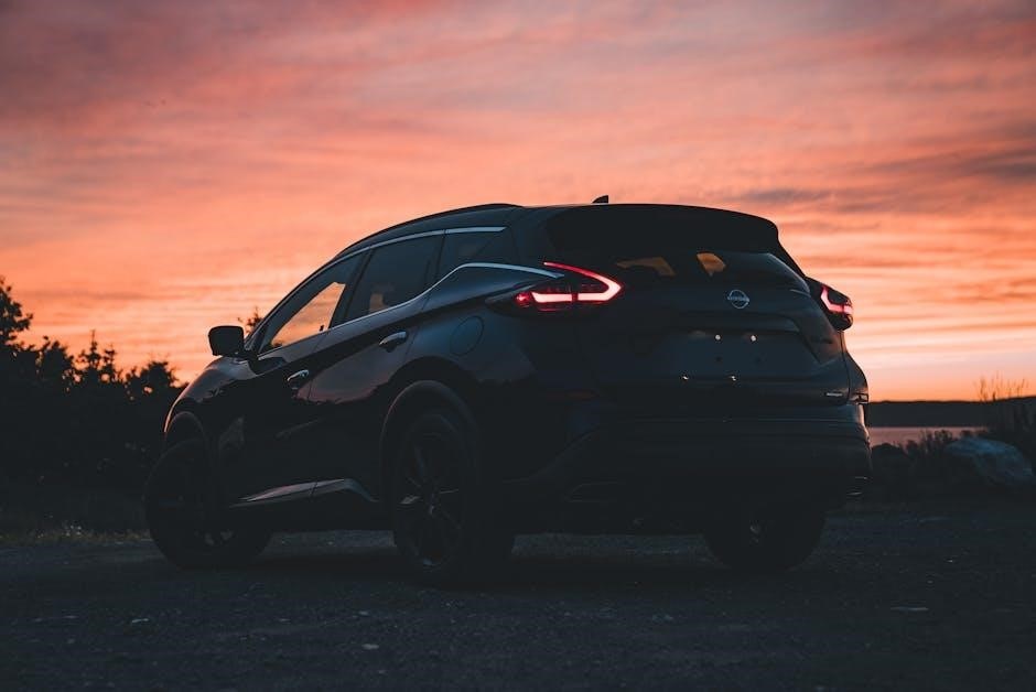
The Nissan Murano 2015 Owners Manual is a comprehensive guide essential for understanding your vehicle’s operation, maintenance, and features. It covers troubleshooting, safety, and optimal performance tips, ensuring a smooth and enjoyable driving experience. This manual is crucial for both new and experienced owners, helping to maximize the vehicle’s potential and longevity.
1.1 Purpose and Importance of the Manual
The Nissan Murano 2015 Owners Manual serves as a vital resource for understanding and maintaining your vehicle. It provides detailed instructions for operating features, troubleshooting issues, and scheduling maintenance. This guide ensures safety, optimal performance, and longevity of the vehicle. By following the manual, owners can address common problems, understand safety protocols, and make informed decisions about their Murano’s care, enhancing overall driving satisfaction and reliability.
1.2 Key Features of the 2015 Nissan Murano
The 2015 Nissan Murano boasts a sleek design, advanced safety features, and a user-friendly infotainment system. It includes a power liftgate for convenience, a robust engine for smooth performance, and a navigation system for seamless travel. The manual highlights these features, ensuring owners can fully utilize their vehicle’s capabilities, from comfort to technology, enhancing the overall driving experience.
Understanding the Dashboard and Controls
The 2015 Nissan Murano features an intuitive dashboard with essential controls for easy operation. The instrument panel displays vital vehicle information, while the infotainment system provides navigation and connectivity options. Understanding these components ensures a safe and enjoyable driving experience, as detailed in the manual.
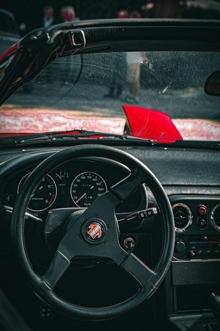
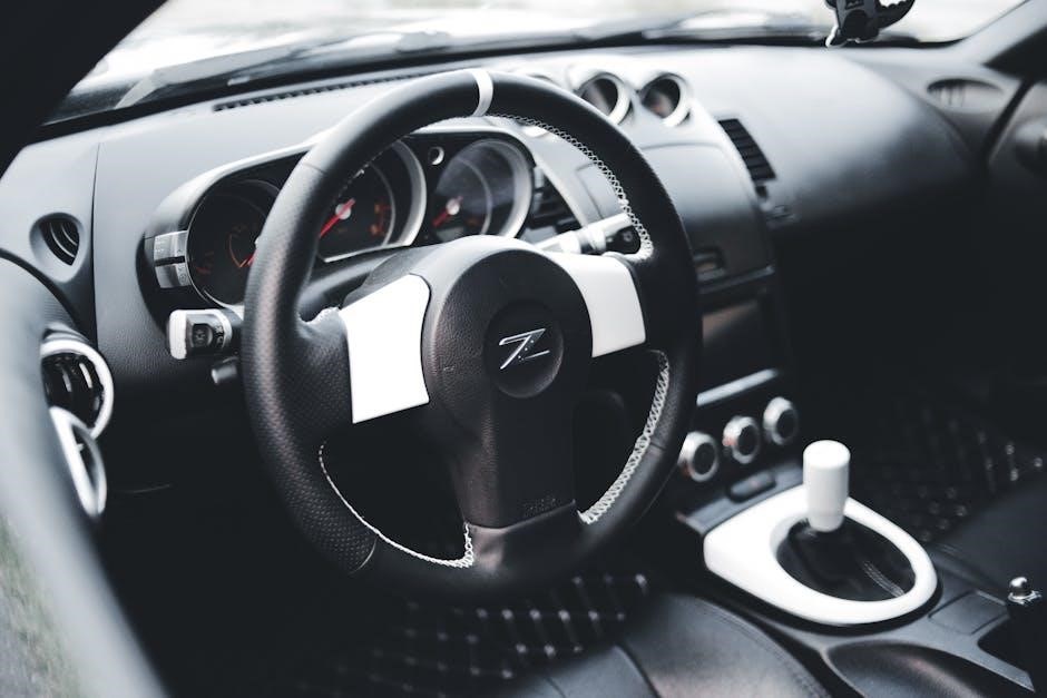
2.1 Overview of the Instrument Panel
The 2015 Nissan Murano’s instrument panel is designed for clarity and convenience. It features a central infotainment display, climate controls, and a driver-focused instrument cluster. The panel includes a speedometer, tachometer, and essential warning lights. Intuitive buttons and knobs allow easy access to navigation, audio, and comfort settings. The layout ensures a seamless driving experience, with all controls within easy reach of the driver.
2.2 Operating the Power Liftgate
The 2015 Nissan Murano’s power liftgate offers convenience with easy operation. To open or close, press the button on the key fob or use the controls on the instrument panel. Ensure the shift lever is in Park and the battery is charged for proper function. The liftgate may reverse if it detects an obstruction, enhancing safety and ease of use.
2.3 Infotainment and Navigation System Basics
The 2015 Nissan Murano’s infotainment system offers a seamless interface for entertainment and navigation. The touch-screen display provides easy access to music, apps, and GPS features. Compatibility with Apple CarPlay and Android Auto enhances smartphone integration. Users can customize the home screen and utilize voice commands for hands-free control. Regular software updates ensure optimal performance and new feature additions, while USB and Bluetooth connectivity provide versatile options for device integration.
Maintenance and Service Schedule
Regular maintenance ensures optimal performance and longevity of your 2015 Nissan Murano. Follow the recommended schedule for oil changes, tire rotations, and inspections to keep your vehicle running smoothly.
3.1 Recommended Maintenance Intervals
Regular maintenance is crucial for your Nissan Murano’s performance. Follow the recommended intervals: oil changes every 5,000 miles, tire rotations every 15,000 miles, and brake inspections every 30,000 miles. Spark plugs should be replaced at 105,000 miles, and the timing belt at 150,000 miles; Adhering to these schedules ensures optimal vehicle health and prevents potential issues. Always consult your manual for specific guidelines.
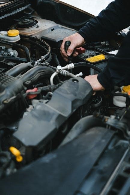
3.2 How to Check and Top Up Fluids
To ensure your Nissan Murano runs smoothly, regularly check essential fluids. Locate the engine oil dipstick under the hood to monitor oil levels. Check coolant, brake, and windshield washer fluids by inspecting their respective reservoirs. Top up as needed, following the manual’s guidelines. Avoid overfilling, as this can cause damage. Always use the recommended fluid types for optimal performance.

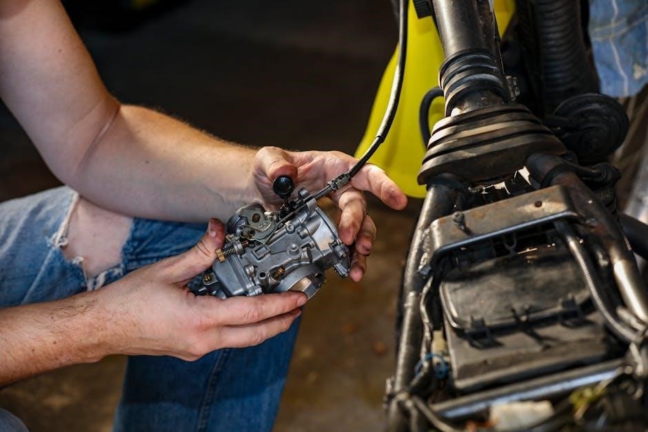
Troubleshooting Common Issues
The manual provides essential guidance for diagnosing and resolving common issues, ensuring your Murano operates at peak performance. It covers solutions for power liftgate, infotainment, and more effectively.
4.1 Power Liftgate Malfunction Solutions
The manual outlines solutions for power liftgate issues, such as ensuring the shift lever is in park and checking battery functionality. It also suggests resetting the system by cycling the ignition and testing the liftgate operation. If problems persist, inspect for obstructions or damaged sensors and consult a certified technician for further assistance to resolve the malfunction effectively.
4.2 Resetting the Maintenance Reminder
To reset the maintenance reminder on your 2015 Nissan Murano, turn the ignition to the “ON” position. Navigate to the “Settings” menu on the instrument panel. Select “Maintenance” and choose the “Reset” option. Confirm the reset, and the reminder should turn off. If the light persists, consult a certified technician to ensure there are no underlying issues.
Safety Features and Precautions
The 2015 Nissan Murano features advanced safety technologies, including electronic stability control and anti-lock braking systems, designed to enhance driver confidence and occupant protection on the road.
5.1 Airbag System and Safety Belts
The 2015 Nissan Murano is equipped with a advanced airbag system, including front, side, and curtain airbags, designed to provide optimal protection during collisions. Safety belts are essential for maximizing occupant safety and must be worn correctly at all times. The manual emphasizes proper belt usage and precautions to ensure the airbag system functions effectively in emergencies, enhancing overall vehicle safety.
5.2 Important Safety Precautions for Drivers
Drivers must ensure all passengers wear safety belts and children are securely fastened in appropriate seats. Avoid distractions while driving, such as using electronic devices. Always maintain a safe following distance and adjust speed according to road conditions. Properly secure cargo to prevent shifting, and never overload the vehicle. Familiarize yourself with controls before driving to ensure safe operation of the 2015 Nissan Murano.
Technical Specifications of the 2015 Nissan Murano
The 2015 Nissan Murano features a 3.5L V6 engine, CVT transmission, and front-wheel or all-wheel drive. It boasts a towing capacity of up to 1,500 lbs, with a fuel tank capacity of 19 gallons and a curb weight of approximately 3,969 lbs.
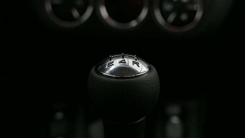
6.1 Engine and Transmission Details
The 2015 Nissan Murano is equipped with a 3.5-liter V6 engine, delivering 260 horsepower and 240 lb-ft of torque. It features an Xtronic CVT (Continuously Variable Transmission) for smooth acceleration. Available in front-wheel drive (FWD) or all-wheel drive (AWD) configurations, the Murano offers balanced performance and efficiency, with an estimated 21 mpg city and 28 mpg highway fuel economy.
6.2 Fuel Efficiency and Performance
The 2015 Nissan Murano achieves an estimated 21 mpg city and 28 mpg highway for front-wheel drive models, while AWD models slightly lower at 20 mpg city and 27 mpg highway. The V6 engine delivers 260 horsepower and 240 lb-ft of torque, providing smooth acceleration. The Xtronic CVT optimizes fuel efficiency and performance, ensuring a responsive and economical driving experience across various conditions.
Using the Navigation System
This section guides users through operating the Nissan Murano’s navigation system, including inputting destinations, using voice commands, and accessing live traffic updates for efficient route planning.
7.1 Inputting Destinations and Voice Commands
Inputting destinations in the 2015 Nissan Murano’s navigation system is straightforward. Use the touchscreen to enter addresses or points of interest manually. Voice commands allow hands-free operation, enabling you to search for locations without taking your eyes off the road. The system recognizes natural speech patterns, making it easy to input destinations efficiently. This feature enhances safety and convenience for drivers.
7.2 Updating the Navigation Software
Updating the navigation software in your 2015 Nissan Murano ensures optimal performance and access to the latest maps. Download updates from Nissan’s official website or via USB. Follow the manual’s instructions to install the update safely. Regular updates enhance system functionality, improve accuracy, and provide a seamless navigation experience. Always use genuine Nissan software to maintain reliability and security.
Accessories and Customization Options
The 2015 Nissan Murano offers genuine accessories to enhance functionality and style. Customize your vehicle with interior upgrades, cargo solutions, and exterior enhancements for a personalized experience.
8.1 Genuine Nissan Accessories
The 2015 Nissan Murano offers a range of genuine accessories designed to enhance functionality and style. These include cargo organizers, floor mats, and exterior trim pieces, all crafted to fit perfectly. Genuine Nissan accessories are built to last, ensuring optimal performance and compatibility. They come with a warranty and are detailed in the manual for easy installation and use, helping owners personalize their vehicle effectively.
8.2 Customizing Your Murano’s Interior
Customizing your 2015 Nissan Murano’s interior enhances comfort and personal style. The manual provides guidance on interior personalization, such as upgrading seats, adding trim accents, or integrating tech features. Owners can explore options like premium materials, cargo organizers, and adjustable seating configurations to tailor the interior to their preferences, ensuring a unique and functional driving environment that reflects their lifestyle.
Downloading the PDF Version of the Manual
The 2015 Nissan Murano Owners Manual is available as a downloadable PDF, offering convenient access to all information. With 420 pages, it ensures comprehensive guidance anytime, anywhere.
9.1 Steps to Download the Manual
To download the 2015 Nissan Murano Owners Manual, visit the official Nissan website and navigate to the owner’s resources section. Log in or create an account to access the manual. Search for the 2015 Murano manual, select the PDF version, and download it. Ensure your device has a PDF reader installed. Some versions may require a password provided upon purchase. This digital copy offers easy access and convenient searching anytime.
9.2 Benefits of a Digital Copy
A digital copy of the 2015 Nissan Murano Owners Manual offers unmatched convenience, allowing instant access from your smartphone, tablet, or computer. It saves physical storage space and reduces clutter. The digital format enables easy searching for specific topics using keywords. Updates can be downloaded as they become available, ensuring you always have the most accurate information. It’s eco-friendly and provides peace of mind with permanent access to your manual.

Comparison with Other Nissan Models
The 2015 Nissan Murano stands out among other models like the Rogue, offering a more powerful V6 engine and refined features, catering to drivers seeking a premium SUV experience with advanced technology and comfort.
10.1 Differences from the 2014 Model
The 2015 Nissan Murano features a redesigned exterior with a more aggressive stance, improved interior amenities, and enhanced technology, including a new infotainment system. It also introduced a refined powertrain and better fuel efficiency compared to the 2014 model. Additional safety features and driver-assistance systems were added, making the 2015 Murano a more modern and capable vehicle overall.
10.2 How the Murano Compares to the Rogue
The Nissan Murano 2015 is positioned as a mid-size crossover, offering a more premium and spacious interior compared to the Rogue, which is a compact SUV. The Murano features a more powerful engine and refined design, targeting buyers seeking luxury and comfort. In contrast, the Rogue focuses on practicality and affordability, making it ideal for smaller families or urban drivers. Both vehicles share Nissan’s reliability but cater to different buyer preferences.
Tips for New Owners
Familiarize yourself with the Murano’s features by exploring the infotainment system, adjusting settings for comfort, and understanding the vehicle’s advanced safety technologies for a smoother experience.
11.1 Getting Familiar with the Vehicle
Take time to explore your Murano’s exterior and interior features, such as the power liftgate, infotainment system, and safety technologies. Familiarize yourself with the dashboard controls, instrument panel, and customizable settings. Reading the manual will help you understand how to personalize your driving experience and make the most of your vehicle’s advanced features and technologies.
11.2 Driving Tips for Optimal Performance
For optimal performance, drive smoothly with gentle acceleration and braking. Maintain proper tire pressure and use the ECO mode for improved fuel efficiency. Avoid extreme temperatures and ensure regular maintenance. Familiarize yourself with the navigation system and safety features to enhance your driving experience. Follow the manual’s recommendations for optimal performance and longevity of your vehicle.
Additional Resources and Support
Nissan offers comprehensive support, including customer service, online forums, and the official website. These resources provide troubleshooting, updates, and community advice to enhance your ownership experience.
12.1 Nissan Customer Service Options
Nissan provides dedicated customer service through various channels, including phone, email, and live chat. Owners can access support 24/7 for inquiries, troubleshooting, and scheduling services. Additionally, the official Nissan website offers extensive resources, such as troubleshooting guides and maintenance tips, ensuring comprehensive assistance for all Murano 2015 owners.
12.2 Online Communities and Forums
Online communities and forums dedicated to the Nissan Murano 2015 provide a platform for owners to share experiences, ask questions, and find solutions. These forums often feature discussions on troubleshooting, maintenance tips, and accessory recommendations. Many owners use these spaces to connect with others, exchange advice, and learn from real-world experiences, fostering a supportive community for Murano enthusiasts.
The Nissan Murano 2015 Owners Manual is a valuable resource for optimizing your vehicle’s performance and longevity. It provides essential insights, ensuring a safe and enjoyable driving experience.
13.1 Final Thoughts on the 2015 Murano
The 2015 Nissan Murano is a refined and versatile vehicle, offering a blend of comfort, technology, and performance. Its comprehensive owners manual serves as an essential guide, ensuring owners can fully utilize its features, maintain it properly, and address any issues efficiently. This manual underscores Nissan’s commitment to providing a seamless and enjoyable ownership experience for the Murano.
13.2 Encouragement to Explore Further
Exploring further resources, such as online forums and Nissan’s official website, can provide additional insights and tips for optimizing your 2015 Murano’s performance. Engage with communities, download updates, and discover new ways to customize your vehicle. Continuous learning enhances your ownership experience, ensuring you maximize the features and capabilities of your Nissan Murano for years to come.